Super Duty Firing Order Ford 6.2 Engine Diagram
Alright, let's dive into the firing order and diagram for the Ford 6.2L "Boss" engine, commonly found in Super Duty trucks. Understanding this is crucial for a variety of tasks, from basic maintenance to more complex diagnostics and modifications. Think of this article as your in-depth guide – we'll cover everything from the engine's anatomy to practical troubleshooting applications. We even have the full diagram available for download, which we'll discuss later.
Purpose of Understanding the Firing Order and Diagram
Why bother with the firing order and diagram? Well, several reasons. First and foremost, it's essential for accurate ignition system maintenance. Knowing the firing order ensures you're replacing spark plugs and checking ignition coils in the correct sequence. It's also vital for diagnosing misfires. If a cylinder isn't firing correctly, understanding the order helps pinpoint the potential issue. Beyond that, it's necessary for:
- Timing Adjustments: Ensuring proper camshaft and crankshaft timing.
- Compression Testing: Interpreting compression test results accurately.
- Fuel Injector Servicing: Identifying and servicing fuel injectors in the correct order.
- Engine Swaps or Rebuilds: Critical for reassembling the engine correctly.
- Performance Modifications: Understanding how modifications might affect engine performance and tuning.
Key Specs and Main Parts of the 6.2L Engine
Before we get to the diagram, let's briefly review some key specifications and the major components of the Ford 6.2L "Boss" engine:
- Engine Type: Gasoline, SOHC (Single Overhead Camshaft), V8
- Displacement: 6.2 Liters (379 cubic inches)
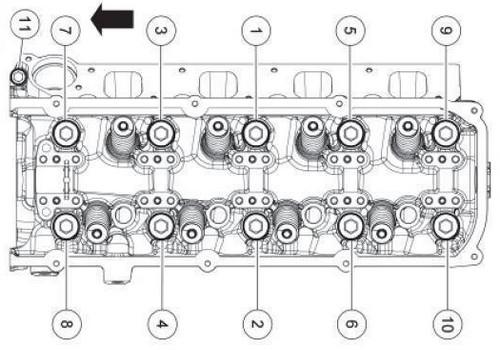
- Firing Order: 1-3-7-2-6-5-4-8
- Cylinder Numbering: (Facing the engine from the front) Right Bank: 1-2-3-4; Left Bank: 5-6-7-8
The major components illustrated in the diagram, and essential to understand, are:
- Cylinders: The core of the engine where combustion occurs.
- Spark Plugs: Provide the spark to ignite the air/fuel mixture.
- Ignition Coils: Step up the voltage to create the spark at the spark plugs.
- Fuel Injectors: Spray fuel into the cylinders.
- Camshaft(s): Operate the valves. The 6.2L is a SOHC engine, meaning each cylinder bank has one camshaft.
- Crankshaft: Converts the linear motion of the pistons into rotational motion.
- PCM (Powertrain Control Module): The engine's computer, controlling ignition timing, fuel injection, and other functions.
Understanding the Symbols in the Diagram
Engine diagrams use a standardized set of symbols to convey information efficiently. Here's a breakdown of common symbols you'll encounter:
- Solid Lines: Typically represent physical connections, such as wiring or fuel lines.
- Dashed Lines: Often indicate vacuum lines or control signals.
- Colors: Wiring diagrams frequently use colors to differentiate between circuits (e.g., red for power, black for ground). You'll find the color codes listed in the diagram legend.
- Component Symbols: These are simplified representations of parts. For instance, a zigzag line within a circle usually denotes a resistor. Squares represent switches and relays.
- Numeric Labels: Clearly identify each cylinder.
- Arrows: Indicate the direction of current flow, fluid flow, or mechanical movement.
Pay close attention to the legend or key included with the diagram. It will explain the specific symbols and color codes used in that particular diagram. Not all diagrams use the exact same conventions.
How It Works: The 6.2L Firing Order Explained
The firing order (1-3-7-2-6-5-4-8) dictates the sequence in which the cylinders ignite the air/fuel mixture. The PCM precisely controls the ignition timing, triggering each ignition coil to fire its corresponding spark plug. This synchronized process ensures smooth engine operation and optimal power output.
Here’s the cycle:
- Cylinder 1 fires: The piston reaches the top of its compression stroke. The spark plug ignites the air/fuel mixture, forcing the piston down.
- Cylinder 3 fires: The process repeats in cylinder 3.
- And so on... through cylinders 7, 2, 6, 5, 4, and finally 8, before returning to cylinder 1 to start the cycle again.
The firing order is crucial for balancing the engine's load and minimizing vibrations. An incorrect firing order will result in a rough-running engine, loss of power, and potential engine damage.
Real-World Use: Basic Troubleshooting Tips
Knowing the firing order and having the diagram handy can save you time and money when troubleshooting engine problems. Here are some common scenarios:
- Misfire Diagnosis: If you're experiencing a misfire (rough idling, loss of power, check engine light), use a scan tool to identify the affected cylinder. Then, check the corresponding spark plug, ignition coil, and fuel injector. The diagram helps you quickly locate the correct components.
- Spark Plug Replacement: Always replace spark plugs in the correct order, following the firing order. This ensures proper engine balance.
- Ignition Coil Testing: Use a multimeter to test the resistance of the ignition coils. The diagram shows you which coil corresponds to which cylinder.
- Crossed Wires: If you've recently worked on the ignition system, double-check that the spark plug wires (if applicable on your model year) are connected to the correct cylinders. A simple mistake can cause a severe misfire.
For example, let's say your scan tool indicates a misfire in cylinder 7. Using the diagram, you can quickly identify the location of cylinder 7 (left bank, towards the rear). You can then systematically check the spark plug, ignition coil, and fuel injector for that cylinder. If the spark plug is fouled, replacing it might solve the problem. If the ignition coil is faulty, replacing it is the next step.
Safety Considerations
Working on the ignition system involves high voltages. Take the following precautions:
- Disconnect the Battery: Always disconnect the negative battery cable before working on any electrical components. This prevents accidental shocks and protects the PCM.
- Avoid Touching Live Wires: Never touch spark plug wires or ignition coils while the engine is running. The voltage can be lethal.
- Use Insulated Tools: Use tools with insulated handles to minimize the risk of electric shock.
- Fuel System Safety: The fuel system is under pressure. If you need to disconnect fuel lines, relieve the pressure first and take precautions to prevent fuel spills. Gasoline is flammable.
The ignition coils are particularly dangerous. They amplify the voltage significantly, so even a brief contact can result in a severe shock. Respect the power of electricity and take all necessary safety precautions.
Getting the Diagram
We have the full, detailed diagram of the Ford 6.2L Super Duty engine firing order and related components ready for you to download. It includes all the details we've discussed, including cylinder numbering, wiring schematics, and component locations. Having this diagram on hand is invaluable for any serious work on your 6.2L engine. Contact us to get the download link. This information, along with this guide, will get you started on the right foot.