Super Duty Ford F250 Front Axle Parts Diagram
Let's dive deep into the anatomy of the Super Duty Ford F250 front axle. Whether you're planning a front-end overhaul, upgrading components, or simply expanding your mechanical knowledge, understanding the front axle parts diagram is crucial. This isn't just about identifying parts; it's about comprehending how they interact, diagnosing issues, and executing repairs safely and effectively. We'll break down the key components, their functions, and how to interpret a typical F250 front axle diagram.
Why Understand the Front Axle Diagram?
The front axle is a critical component, especially in a 4x4 vehicle like the F250. Understanding its diagram is essential for several reasons:
- Repairs and Maintenance: Accurately identify the faulty part for efficient replacement.
- Upgrades and Modifications: Ensures compatibility when upgrading components like ball joints, steering knuckles, or even the entire axle assembly.
- Troubleshooting: Pinpoint the source of noises, vibrations, or steering issues.
- Learning: A deeper understanding of the vehicle's mechanics enhances your diagnostic skills and overall mechanical knowledge.
- Cost Savings: Informed DIY repairs can save significant labor costs.
Key Specs and Main Parts of the F250 Front Axle
The Super Duty F250 typically utilizes a solid front axle, also known as a beam axle. This robust design is chosen for its strength and durability, crucial for heavy-duty applications.
Main Components:
- Axle Housing: The primary structural component, housing the differential and axle shafts. It's typically a heavy-duty steel construction.
- Differential: Allows the wheels to rotate at different speeds during turns. F250s often come with open differentials, limited-slip differentials (LSDs), or electronic locking differentials.
- Axle Shafts: Transmit power from the differential to the wheels. These are hardened steel shafts designed to withstand significant torque.
- Universal Joints (U-Joints): Connect the axle shafts to the wheel hubs, allowing for articulation as the suspension moves. These are critical for 4x4 operation.
- Wheel Hubs: Connect the wheels to the axle assembly. They contain bearings that allow the wheels to rotate freely.
- Steering Knuckles: Connect to the wheel hubs and allow the wheels to be steered.
- Ball Joints: Allow the steering knuckle to pivot, enabling steering. There are typically upper and lower ball joints on each side.
- Tie Rods and Drag Link: Part of the steering linkage that transmits movement from the steering box to the steering knuckles.
- Steering Stabilizer: A shock absorber that dampens vibrations in the steering system, improving stability.
- Track Bar (Panhard Rod): Locates the axle laterally, preventing it from shifting side-to-side.
- Coil Springs (or Leaf Springs in older models): Provide suspension and support the vehicle's weight.
- Shocks: Dampen suspension movement, controlling bounce and improving ride quality.
- Brake Components: Including calipers, rotors, pads, and brake lines. Vital for stopping the vehicle.
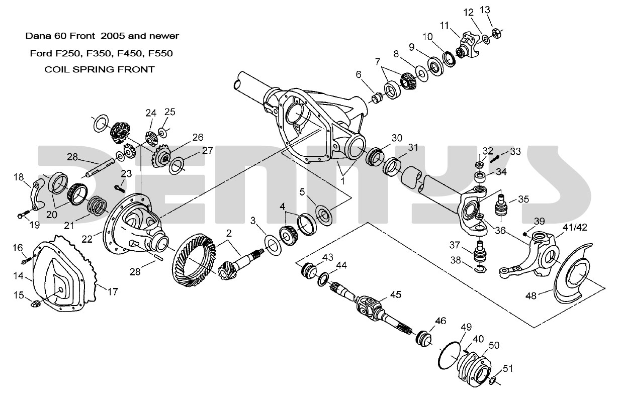
Decoding the Front Axle Diagram: Symbols and Conventions
Understanding the symbols used in a parts diagram is essential for accurate identification. Here's a breakdown of common conventions:
- Solid Lines: Typically represent solid components like the axle housing, shafts, and steering linkages.
- Dashed Lines: Often indicate hidden parts or components that are connected behind other parts in the diagram.
- Arrows: Show the direction of force or movement, such as the flow of power from the differential to the wheels.
- Numbers and Callouts: Correspond to a parts list, providing the part number and description. Always verify the part number with your specific F250's VIN to ensure compatibility.
- Exploded Views: Illustrate how the components fit together in an exploded view, making assembly and disassembly easier to visualize.
- Colors: While less common in older diagrams, newer diagrams sometimes use colors to differentiate systems (e.g., blue for hydraulic lines, red for electrical wires).
Important: Pay close attention to the diagram's key or legend. This will explain any specific symbols or notations used.
How the Front Axle Works: A Simplified Explanation
The F250's front axle works by receiving power from the transfer case (in 4x4 models) or directly from the transmission (in 2WD models). The power flows through the differential, which splits the torque between the two axle shafts. The axle shafts, connected to the wheels via U-joints and hubs, rotate the wheels, propelling the vehicle.
The differential allows the wheels to rotate at different speeds when cornering. When the vehicle turns, the outside wheel travels a greater distance than the inside wheel. The differential allows the outside wheel to rotate faster, preventing binding and tire wear. In a limited-slip differential or locking differential, this speed difference can be controlled or eliminated, providing enhanced traction in off-road conditions.
The steering system, connected to the steering knuckles via tie rods and the drag link, allows the driver to control the direction of the front wheels. The ball joints provide the necessary articulation for steering, while the steering stabilizer dampens vibrations for a smoother ride.
Real-World Use: Basic Troubleshooting Tips
Using the front axle diagram, you can begin to diagnose common issues:
- Clicking Noise When Turning: Often indicates a worn U-joint. Inspect the U-joints for looseness or play.
- Vibrations: Could be caused by unbalanced wheels, a bent axle shaft, or worn wheel bearings. Check the wheel balance and inspect the axle shaft for damage. Worn wheel bearings often produce a rumbling noise that increases with speed.
- Steering Wander or Looseness: Could be due to worn ball joints, tie rod ends, or a loose track bar. Have the ball joints and tie rod ends inspected for play. Check the track bar mounting points for looseness.
- Leaking Differential Fluid: Inspect the differential housing for cracks or leaks. Check the axle seals for leaks.
Remember: A thorough visual inspection is the first step in any troubleshooting process. Use the diagram to identify the components and their locations.
Safety First: Highlighting Risky Components
Working on the front axle involves dealing with heavy components and potential hazards. Always prioritize safety:
- Springs: Coil springs and leaf springs store a tremendous amount of energy. Improper handling can lead to serious injury. Always use proper spring compressors when removing or installing springs. Never attempt to compress springs without the correct tools.
- Brake System: Brake fluid is corrosive and can damage paint. Use caution when working with brake lines and calipers. Always bleed the brakes after working on the brake system.
- Lifting the Vehicle: Use jack stands to support the vehicle. Never work under a vehicle supported only by a jack.
- Tightening Torque: Always tighten fasteners to the manufacturer's specified torque. Using the correct torque ensures proper component clamping and prevents premature failure. Refer to a service manual for torque specifications.
- Eye Protection: Always wear safety glasses to protect your eyes from debris.
- Wheel Hubs: Many newer F250s have unit bearings. These are often pressed into the steering knuckle and require specialized tools for removal and installation.
The front axle of your F250 is a robust system, but proper maintenance and informed repairs are essential for its longevity and your safety. By understanding the parts diagram and the function of each component, you'll be well-equipped to tackle a range of repairs and upgrades.
Want to delve even deeper? We have a detailed front axle parts diagram available for download. This diagram is a valuable resource for visualizing the assembly and identifying specific parts. Contact us to request the file. Good luck with your project!