
Suzuki Ignition Switch Wiring Diagram
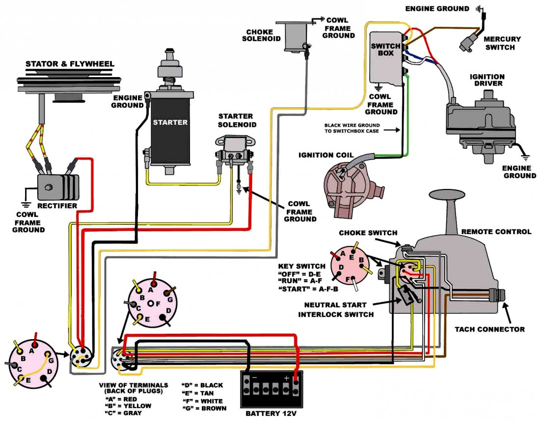
Understanding your Suzuki's ignition switch wiring diagram is crucial for various tasks, from simple repairs to more complex modifications. Whether you're chasing down an electrical gremlin, installing an aftermarket security system, or just trying to better understand your vehicle's electrical architecture, this knowledge is invaluable. This article will provide a detailed breakdown of a typical Suzuki ignition switch wiring diagram, equipping you with the information you need to tackle these tasks confidently.
Why This Diagram Matters
The ignition switch is the heart of your Suzuki's electrical system. It's the gatekeeper, controlling the flow of power to various circuits depending on the key's position. A malfunctioning ignition switch can cause a multitude of problems, including a no-start condition, intermittent electrical failures, and even battery drain. Having the wiring diagram allows you to:
- Diagnose Electrical Issues: Pinpoint faults in the ignition circuit quickly.
- Perform Repairs: Replace damaged wiring or the switch itself with confidence.
- Install Accessories: Tap into the correct circuits for aftermarket accessories like remote starters or alarms.
- Understand Your Vehicle: Gain a deeper understanding of how your Suzuki's electrical system operates.
Key Specs and Main Parts of a Typical Suzuki Ignition Switch Circuit
While the specific wiring may vary depending on the Suzuki model and year, the fundamental principles remain consistent. Here's a breakdown of the key components and their typical functions:
- Battery (B+): The source of power, typically connected via a fusible link or main fuse. This wire is always hot. It's crucial to disconnect the battery before working on the electrical system!
- Ignition Switch: The mechanical switch with multiple positions controlled by the key:
- Lock: No circuits are powered. Steering wheel lock engaged (if equipped).
- ACC (Accessory): Powers accessories like the radio and wipers.
- ON (Run): Powers the ignition system, fuel pump, and other essential components for running the engine.
- START: Powers the starter solenoid to crank the engine.
- Starter Solenoid: An electromagnetic switch that engages the starter motor.
- Ignition Coil: Steps up the voltage from the battery to create the spark needed for combustion.
- ECU (Engine Control Unit): The "brain" of the engine, controlling various functions like fuel injection and timing. (Often indirectly powered through the ignition switch)
- Fuses and Relays: Protective devices that prevent damage from overcurrents and control high-current circuits with low-current signals.
- Ground (GND): Provides a return path for the electrical current to the battery. A good ground connection is essential for proper operation.
Deciphering the Symbols in the Wiring Diagram
Wiring diagrams use standardized symbols and conventions. Understanding these is key to interpreting the diagram correctly.
- Lines: Represent wires. Thicker lines often indicate higher current-carrying capacity.
- Colors: Each wire is assigned a color code (e.g., Red = RD, Blue = BL, Black = BK, Yellow = YL, Green = GR, White = W). This helps you identify wires in the vehicle. A stripe color may be indicated as well (e.g., RD/BL = Red with a Blue stripe).
- Circles: Represent connections or splices in the wiring.
- Rectangles: Typically represent components like relays, fuses, and switches.
- Ground Symbol: Often depicted as a series of horizontal lines decreasing in length, indicating a connection to the vehicle's chassis.
- Component Symbols: Vary depending on the component (e.g., a coil symbol for an ignition coil, a motor symbol for the starter motor). These are usually labeled.
- Numbers and Letters: May indicate wire gauge (AWG) or circuit identification numbers.
How It Works: Power Flow Through the Ignition Switch
Let's trace the power flow through a simplified ignition circuit:
- When the key is in the LOCK position, no circuits are energized (except potentially the clock or security system which may have a separate always-on feed).
- Turning the key to the ACC position connects the battery power (B+) to the accessory circuit. This allows you to use the radio, wipers, etc., without the engine running.
- Turning the key to the ON position connects the battery power (B+) to the ignition and fuel system circuits. This energizes the ECU, fuel pump, and ignition coil, preparing the engine to start.
- Turning the key to the START position connects the battery power (B+) to both the ignition/fuel circuits *and* the starter solenoid circuit. This engages the starter motor, cranking the engine. Once the engine starts, you release the key, and it springs back to the ON position.
The ignition switch essentially acts as a multi-pole, multi-throw switch, directing power to different circuits based on the key position. The complexity lies in the specific circuits that are energized in each position and the interlocks and safety features incorporated into the system (e.g., a clutch switch that prevents starting unless the clutch is depressed).
Real-World Use: Basic Troubleshooting Tips
Here are some common problems and how the wiring diagram can help you troubleshoot them:
- No Start: Check if the starter motor is receiving power when the key is in the START position. Use a multimeter to test for voltage at the starter solenoid. If there's no voltage, trace the wire back to the ignition switch and check for continuity and voltage. Consult the diagram to identify the correct wire and test points.
- No Power to Accessories: If accessories don't work in the ACC position, check the fuse for the accessory circuit. If the fuse is good, use the diagram to trace the power flow from the ignition switch to the accessory circuit.
- Battery Drain: A faulty ignition switch can sometimes cause a parasitic draw, draining the battery even when the car is off. Disconnect the battery and use a multimeter to measure the current draw. Then, systematically disconnect circuits powered by the ignition switch (starting with the accessories) to isolate the source of the draw.
- Intermittent Problems: Look for loose connections, corroded terminals, or damaged wiring. The wiring diagram can help you identify the specific wires and connectors to inspect. Wiggle testing wiring harnesses while observing for changes in electrical behaviour is helpful.
Safety First! Highlighting Risky Components
Working with automotive electrical systems can be dangerous. Always remember:
- Disconnect the Battery: Before starting any electrical work, disconnect the negative battery cable to prevent short circuits and electrical shocks.
- Be Careful with Airbags: Many Suzuki vehicles have airbags connected to the ignition system. Incorrectly disconnecting or reconnecting wires can trigger the airbags, causing serious injury. Consult the service manual for proper airbag disabling procedures before working near these components.
- Use the Right Tools: Use a multimeter to test for voltage and continuity. Use proper wire strippers and crimpers for making connections.
- Work in a Well-Ventilated Area: When soldering, work in a well-ventilated area to avoid inhaling fumes.
- Double-Check Your Work: Before reconnecting the battery, carefully double-check all connections and wiring to ensure they are correct.
The B+ wire connected to the ignition switch is a high-current circuit and can cause significant damage or injury if shorted to ground. Exercise extreme caution when working with this wire. Always verify the wire you are testing with the wiring diagram. Color codes are useful but should always be verified against the diagram. Also consider the vehicle's age; wire colors can fade or become discolored.
This article provides a general overview of Suzuki ignition switch wiring diagrams. Specific details may vary depending on the model and year of your vehicle. Always refer to the factory service manual for the most accurate and up-to-date information.
We have a sample Suzuki ignition switch wiring diagram file available for download. This file will give you a visual aid to complement the information in this article. Download this diagram to better understand the concepts we have discussed.