
Switch Fuel Pump Relay Wiring Diagram
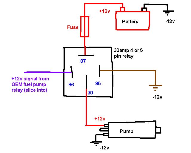
Understanding the fuel pump relay wiring diagram is crucial for any serious car owner, modder, or DIY mechanic. It’s your roadmap to diagnosing and repairing fuel delivery issues, a common culprit behind starting problems and poor engine performance. Whether you're troubleshooting a no-start condition, upgrading your fuel system, or simply deepening your automotive knowledge, a solid grasp of this diagram is indispensable. This article will break down the key components, symbols, and workings of a typical fuel pump relay circuit, giving you the confidence to tackle fuel system challenges.
Purpose: Why You Need to Understand This Diagram
The fuel pump relay wiring diagram isn't just a piece of paper; it's the key to unlocking a deeper understanding of your vehicle's fuel system. Its primary purposes include:
- Troubleshooting Fuel Delivery Problems: When your engine refuses to start, sputters, or lacks power, the fuel pump is often a prime suspect. The diagram allows you to systematically trace the circuit and identify faulty components like a bad relay, wiring issue, or even a failing ECM (Engine Control Module).
- Performing Fuel System Upgrades: Upgrading to a high-performance fuel pump or adding aftermarket fuel injectors often requires modifying the existing wiring. The diagram provides the necessary information to do so safely and correctly, ensuring proper voltage and current delivery.
- Preventing Costly Repairs: Identifying and fixing a minor wiring issue before it escalates into a major problem can save you significant money in the long run. Early diagnosis can prevent damage to other components, such as the fuel pump itself or the ECM.
- Educational Purposes: Learning how a fuel pump relay circuit works gives you a deeper understanding of automotive electrical systems in general. The principles learned here can be applied to other circuits in your vehicle.
Key Specifications and Main Parts
A typical fuel pump relay circuit consists of several key components, each with its own function:
- Battery: The power source for the entire circuit, typically providing 12V DC.
- Ignition Switch: A switch that controls the flow of power to various circuits when the key is turned to the "on" or "start" position.
- Fuel Pump Relay: An electromagnetic switch that controls the high-current circuit powering the fuel pump. It consists of a coil (the electromagnet) and a set of contacts (the switch).
- ECM (Engine Control Module): The "brain" of the engine, responsible for controlling various functions, including the fuel pump relay. It sends a signal to activate the relay based on engine conditions.
- Fuel Pump: An electric pump located inside the fuel tank that draws fuel from the tank and delivers it to the engine.
- Inertia Switch (Optional): A safety device designed to cut power to the fuel pump in the event of a collision. This prevents fuel from being pumped in the event of a fuel line rupture.
- Fuses: Overcurrent protection devices designed to protect the circuit from damage. A blown fuse indicates a problem in the circuit.
- Wiring: The conductive pathways that connect all the components together. Wire gauge (thickness) is important to ensure adequate current-carrying capacity.
Decoding the Symbols in the Wiring Diagram
Understanding the symbols used in the diagram is crucial for interpreting the circuit layout. Here's a breakdown of common symbols:
- Lines: Represent wires. Thicker lines often indicate wires that carry more current. Dashed lines might represent ground connections.
- Colors: Each wire is typically identified by a color code (e.g., Red, Black, Blue/White). This helps you trace the wires in the actual vehicle.
- Battery Symbol: Represented by alternating long and short lines. Indicates the power source.
- Relay Symbol: A rectangle with a coil inside and a switch connected to the coil. Shows how the relay activates the circuit.
- Fuse Symbol: Zigzag line inside a rectangle or a rounded rectangle. Indicates a fuse for circuit protection.
- Ground Symbol: Looks like a series of downward-pointing lines connected to each other. Shows where the circuit is grounded to the vehicle chassis.
- ECM Symbol: Often represented by a box with multiple input/output pins.
Note: Symbols can vary slightly depending on the diagram's source, but the basic principles remain the same.
How It Works: Tracing the Fuel Pump Relay Circuit
Let's trace the operation of a typical fuel pump relay circuit:
- When the ignition switch is turned to the "on" or "start" position, power is supplied to the ECM.
- The ECM monitors various engine parameters, such as engine speed (RPM) and crankshaft position. If these parameters meet the ECM's criteria for engine operation, it sends a ground signal to the fuel pump relay coil.
- When the relay coil receives the ground signal, it creates an electromagnetic field, which pulls the relay's contacts closed.
- Closing the relay contacts completes the high-current circuit from the battery, through a fuse, to the fuel pump.
- The fuel pump then activates, drawing fuel from the tank and delivering it to the engine.
- Once the engine is running, the ECM continues to monitor engine parameters and maintains the ground signal to the relay coil, keeping the fuel pump running.
- If the engine stalls or the inertia switch is tripped, the ECM removes the ground signal to the relay coil, de-energizing the relay and stopping the fuel pump.
Real-World Use: Basic Troubleshooting Tips
Using the wiring diagram, you can perform basic troubleshooting steps:
- No Fuel Pump Operation: If the fuel pump isn't running, first check the fuel pump fuse. If it's blown, replace it and see if it blows again. A repeatedly blown fuse indicates a short circuit.
- Check the Relay: You can test the relay by applying 12V to the coil terminals and listening for a "click." You can also use a multimeter to check the continuity of the contacts when the relay is energized.
- Test for Voltage at the Fuel Pump: Use a multimeter to check for voltage at the fuel pump connector when the ignition is turned on. If there's no voltage, the problem is likely upstream in the circuit (relay, wiring, ECM).
- Check the Ground Connection: Ensure the fuel pump has a good ground connection. A poor ground can cause intermittent or weak fuel pump operation.
- Inertia Switch: If your vehicle has an inertia switch, check to see if it has been tripped. Reset it if necessary.
Safety Considerations: Highlighting Risky Components
Working with automotive electrical systems involves inherent risks. Keep these safety tips in mind:
- Disconnect the Battery: Always disconnect the negative battery terminal before working on any electrical component. This prevents accidental short circuits and potential damage.
- Work in a Well-Ventilated Area: Fuel vapors are flammable and can be harmful if inhaled.
- Use Proper Tools: Use insulated tools to avoid electric shock.
- Be Careful with Fuel Lines: When disconnecting fuel lines, relieve the pressure in the system first. Wear safety glasses to protect your eyes from fuel spray.
- Never Smoke or Use Open Flames: Fuel vapors are highly flammable.
High-Risk Components: The fuel pump itself, wiring near the fuel tank, and the inertia switch (if equipped) require extra caution due to the proximity of fuel.
Understanding the fuel pump relay wiring diagram empowers you to diagnose and repair fuel system issues effectively. By familiarizing yourself with the components, symbols, and operation of the circuit, you'll be well-equipped to tackle a wide range of automotive challenges.
We have a detailed, downloadable fuel pump relay wiring diagram available for reference. This diagram provides a visual aid and further clarifies the concepts discussed in this article. It includes common wire colors and connector locations for a variety of vehicles.