
Switch With Pilot Light Wiring Diagram
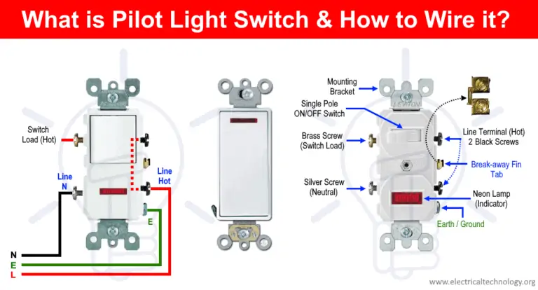
Wiring diagrams might seem intimidating at first glance, but they're invaluable tools for any serious DIY mechanic or car enthusiast. This article focuses on a specific, yet common, type of circuit: the switch with pilot light. Understanding this circuit is essential for various automotive projects, from adding auxiliary lights to troubleshooting electrical problems. We'll break down the diagram, explain the components, and provide practical troubleshooting tips. By the end, you'll be able to read and understand this type of wiring diagram, empowering you to tackle more complex automotive electrical tasks.
Purpose of the Switch with Pilot Light Wiring Diagram
This particular wiring diagram serves several critical purposes:
- Troubleshooting Existing Circuits: If your accessory (e.g., fog lights, aftermarket stereo) powered by a switch with a pilot light isn't functioning correctly, this diagram helps you trace the wiring, identify potential faults (like shorts, opens, or bad grounds), and pinpoint the source of the problem.
- Installing New Accessories: Planning to add new fog lights, interior lights, or any other electrical accessory controlled by a switch with a pilot light? This diagram provides a clear roadmap for proper wiring, ensuring safe and reliable operation.
- Learning Automotive Electrical Principles: Understanding the switch with pilot light circuit is a fundamental step in grasping broader automotive electrical concepts. It introduces basic circuit principles like power flow, grounding, and the role of switches and indicators.
- Modifying Existing Circuits: Want to change the wiring of your existing switch and pilot light setup? This diagram provides the necessary information to make informed modifications while maintaining safe and reliable operation.
Key Specs and Main Parts
Before diving into the diagram itself, let's define the key components and specifications involved in a typical switch with pilot light circuit:
- Power Source (Typically +12V DC): This is usually the vehicle's battery, providing the necessary voltage to operate the accessory and the pilot light. Often, a fuse is included in this line to protect the circuit.
- Fuse: A safety device designed to protect the circuit from overcurrent. If the current exceeds the fuse's rating, the fuse element melts, breaking the circuit and preventing damage to the wiring and components. (e.g., 5A, 10A, 15A - chosen based on the load of the accessory)
- Switch: A mechanical device that opens or closes a circuit, allowing or preventing the flow of electricity. SPST (Single Pole Single Throw) and SPDT (Single Pole Double Throw) switches are common. SPST switches simply connect or disconnect the circuit. SPDT switches have three terminals and can connect one terminal to either of the other two.
- Pilot Light (Indicator Lamp): A small light, typically an LED or incandescent bulb, that illuminates to indicate whether the accessory is on or off. Its operating voltage must match the vehicle's voltage (usually 12V).
- Accessory (Load): The device being powered by the circuit (e.g., fog lights, driving lights, interior lights, radio). The current draw (Amperage) of the accessory is a critical specification for selecting appropriate wiring and fuse sizes.
- Ground (Chassis Ground): The return path for the electrical current, typically connected to the vehicle's metal chassis. A good ground connection is essential for proper circuit operation.
- Wiring: Automotive-grade wire, sized appropriately for the current load. AWG (American Wire Gauge) is a common specification for wire size. Lower AWG numbers indicate thicker wires that can carry more current.
Symbols Explained
Understanding the symbols used in the wiring diagram is crucial for interpreting it correctly. Here's a breakdown of common symbols:
- Straight Lines: Represent wires. The thickness of the line might, in some diagrams, represent the wire gauge, but this is not always the case.
- Dotted Lines: Often indicate wires that are optional or are part of a separate sub-circuit.
- Circles: Can represent various components, depending on what's inside the circle. A circle with an "X" inside typically represents a lamp (like the pilot light).
- Zigzag Line: Represents a resistor. In the context of a pilot light, a resistor might be used to limit the current flowing through the LED to prevent it from burning out.
- Ground Symbol (Usually a downward-pointing triangle or stacked lines): Indicates a connection to the vehicle's chassis ground.
- Switch Symbol (Typically a line that can be toggled): Represents the switch's contacts. The position of the line indicates whether the switch is open or closed.
- Fuse Symbol (Often a squiggly line inside a rectangle): Represents the fuse.
- Battery Symbol (Series of long and short parallel lines): Represents the vehicle's battery. The longer line indicates the positive (+) terminal, and the shorter line indicates the negative (-) terminal.
- Color Codes: Wires are often color-coded to aid in identification. Common color codes include:
- Red: Typically used for positive (+) power wires.
- Black: Typically used for ground (-) wires.
- Other Colors (e.g., Blue, Green, Yellow, White): Used for various signal or accessory wires. The specific color code used can vary depending on the vehicle manufacturer.
Note: Wire color conventions can vary between manufacturers and even within different models from the same manufacturer. Always double-check the wiring diagram specific to your vehicle.
How It Works
The basic principle of a switch with a pilot light circuit is relatively straightforward:
- Power Flow: Power flows from the battery (positive terminal) through a fuse to protect the circuit.
- Switch Control: The fused power then goes to the switch. When the switch is in the "on" position, it completes the circuit, allowing current to flow to the accessory (load).
- Accessory Operation: The accessory receives power and operates (e.g., the fog lights turn on).
- Pilot Light Illumination: A branch of the circuit is connected to the pilot light. This branch can be configured in two primary ways:
- Pilot Light ON When Accessory is ON: The pilot light is wired in parallel with the accessory. When the switch is closed and the accessory receives power, the pilot light also receives power and illuminates.
- Pilot Light ON When Accessory is OFF: This requires a slightly more complex wiring configuration, often using an SPDT switch. The pilot light is wired to the terminal that is *not* connected to the accessory when the switch is in the "off" position. When the switch is flipped "on," power is diverted to the accessory, and the pilot light turns off.
- Ground Return: After passing through the accessory and the pilot light, the current returns to the battery's negative terminal through the vehicle's chassis ground.
Real-World Use and Basic Troubleshooting
Here are some practical troubleshooting tips based on understanding the switch with pilot light wiring diagram:
- Accessory Not Working, Pilot Light Not On:
- Check the fuse. A blown fuse is the most common cause.
- Verify the switch is in the "on" position.
- Check the ground connection for the accessory and the pilot light. Ensure the connection is clean and secure.
- Use a multimeter to check for voltage at the switch input and output terminals when the switch is on. No voltage at the input means a problem upstream (fuse, wiring). No voltage at the output means a faulty switch.
- Accessory Not Working, Pilot Light IS On:
- This indicates that the switch and pilot light circuit are functioning, but the accessory itself is not.
- Check the wiring connections to the accessory.
- Test the accessory directly by applying power and ground to it, bypassing the switch and pilot light circuit. If it still doesn't work, the accessory is faulty.
- Pilot Light Not Working, Accessory IS On:
- Check the pilot light bulb or LED. It may be burned out.
- Check the wiring connections to the pilot light.
- Use a multimeter to check for voltage at the pilot light terminals when the accessory is on. No voltage indicates a wiring problem or a faulty switch contact related to the pilot light circuit.
Safety Considerations
Working with automotive electrical systems can be dangerous. Here are some crucial safety precautions:
- Disconnect the Battery: Always disconnect the negative terminal of the battery before working on any electrical circuits. This prevents accidental shorts and potential electrical shocks.
- Work in a Well-Ventilated Area: Batteries can produce explosive gases. Ensure adequate ventilation to prevent the buildup of these gases.
- Use Proper Tools: Use insulated tools designed for automotive electrical work.
- Protect Yourself: Wear safety glasses to protect your eyes from sparks or debris.
- Avoid Working on Live Circuits: Unless absolutely necessary for testing, avoid working on live circuits. If you must work on a live circuit, exercise extreme caution and use appropriate safety measures.
- Be Mindful of Wire Gauges: Always use wire gauges appropriate for the current load. Using undersized wires can lead to overheating and potential fire hazards.
- The Airbag System: Be extremely cautious when working near airbags. Disconnect the battery and wait at least 10 minutes before working on any wiring near the airbag system. Consult your vehicle's service manual for specific airbag safety procedures. Improper handling of airbags can result in serious injury.
Remember, if you are unsure about any aspect of automotive electrical work, consult a qualified mechanic. Electrical problems can be complex and potentially dangerous, so it's always best to err on the side of caution.
We have a downloadable PDF file of the switch with pilot light wiring diagram, including variations and common implementations. Feel free to download it to have a ready reference for your projects and troubleshooting needs. Understanding this diagram will undoubtedly boost your confidence and competence in tackling automotive electrical tasks.