
Tekonsha Trailer Brake Controller Wiring
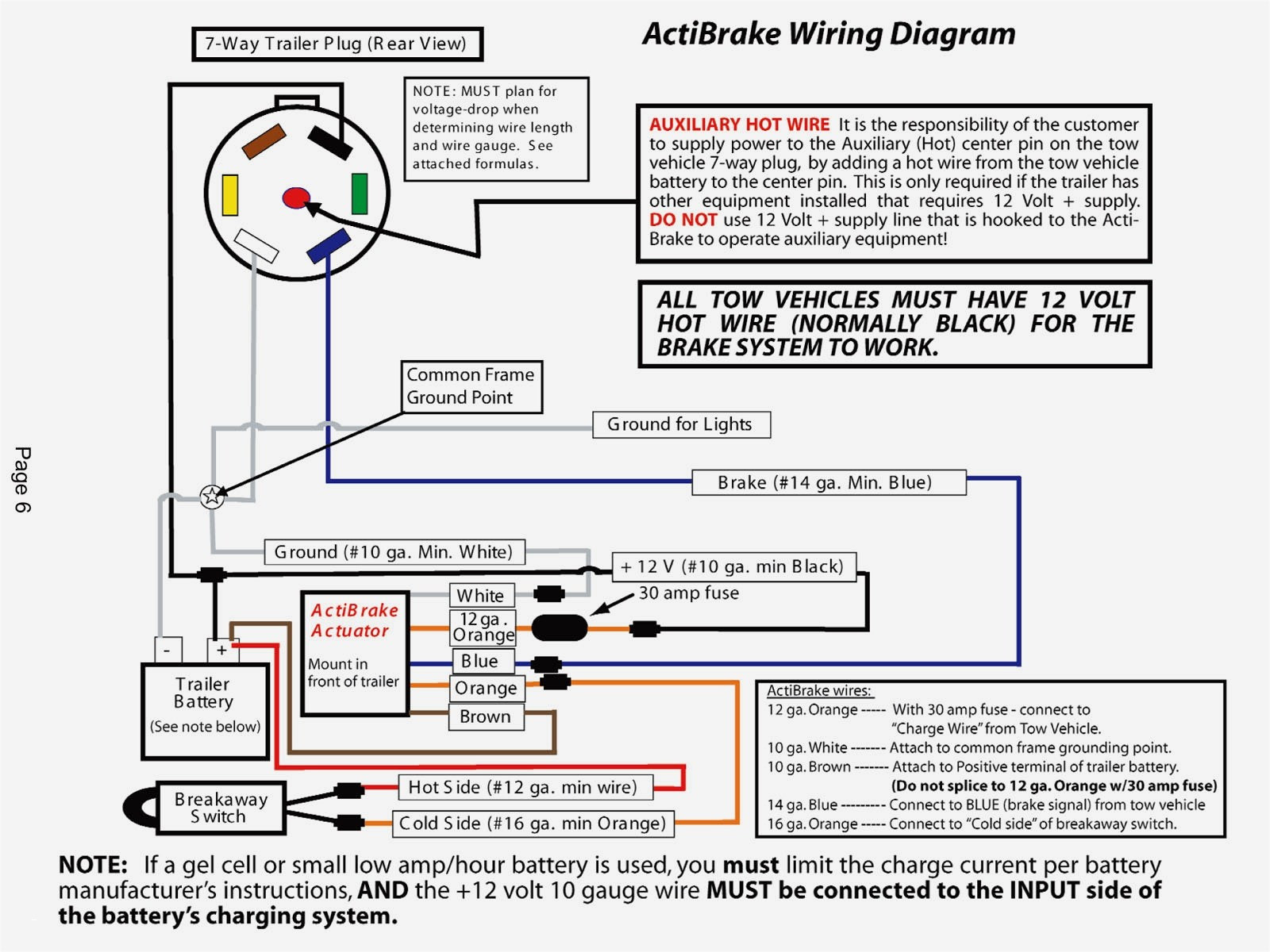
Understanding and correctly wiring a Tekonsha trailer brake controller is crucial for safe and effective towing. Whether you're tackling a new installation, diagnosing a fault, or simply want a deeper understanding of your towing setup, this guide will provide you with the knowledge and confidence to handle Tekonsha brake controller wiring like a pro. We'll break down the components, wiring diagram conventions, and troubleshooting steps, all while keeping safety paramount.
Purpose of Understanding Tekonsha Brake Controller Wiring
Why bother diving into the intricacies of brake controller wiring? Several compelling reasons exist:
- New Installation: The most obvious reason. Ensuring a correct installation from the get-go prevents future headaches and ensures your trailer brakes function as intended.
- Troubleshooting: When trailer brakes malfunction (weak braking, no braking, or always-on braking), understanding the wiring allows you to pinpoint the source of the problem.
- Repair and Maintenance: Damaged wiring, corroded connections, or faulty components necessitate a solid understanding of the wiring diagram for effective repair.
- Upgrades and Modifications: Maybe you're upgrading to a different brake controller model or adding additional features to your trailer wiring. Knowing the existing layout is essential.
- Educational: Gaining a thorough understanding of your vehicle's electrical systems, including trailer braking, empowers you to be a more informed and capable DIYer.
Key Specs and Main Parts of a Tekonsha Brake Controller System
Before we delve into the wiring diagram itself, let's familiarize ourselves with the key components and their specifications:
Main Parts:
- Brake Controller Unit: This is the brain of the system. It senses the vehicle's deceleration and applies proportional braking force to the trailer brakes. Tekonsha offers a range of controllers, from simple time-delayed models to sophisticated proportional units like the Primus IQ or Prodigy P3.
- Wiring Harness: The harness connects the brake controller to the vehicle's electrical system and the trailer connector. These are often sold as vehicle-specific harnesses for easier installation.
- Trailer Connector (Typically a 7-Way Blade Connector): This connector provides the electrical interface between the tow vehicle and the trailer. It carries signals for brake lights, turn signals, running lights, ground, 12V power, and, most importantly, the trailer brake signal.
- Trailer Brakes: These are typically electric drum brakes located on the trailer axles. They receive the braking signal from the controller and apply braking force.
- Tow Vehicle Brake Light Switch: This switch detects when the vehicle's brake pedal is pressed and sends a signal to the brake controller.
- Fuses and Circuit Breakers: These are crucial for protecting the system from overcurrents and short circuits.
Key Specifications:
- Voltage: Typically 12V DC (Direct Current).
- Amperage Rating: The brake controller will have a maximum amperage rating for the trailer brakes it can control. Exceeding this rating can damage the controller and the wiring. This rating is typically found in the controller's documentation.
- Wiring Gauge: Using the correct wire gauge is vital. Undersized wires can overheat and cause voltage drop, leading to inadequate braking. Refer to the brake controller's manual for recommended wire gauges based on trailer weight and wiring distance.
Understanding Wiring Diagram Symbols and Conventions
Wiring diagrams use standardized symbols to represent components and connections. Let's decipher some common ones:
- Solid Lines: Represent wires. The thickness of the line *does not* typically indicate wire gauge in basic diagrams.
- Dashed Lines: Might represent shielded cables or wires that are physically routed in a specific way (e.g., inside a chassis).
- Circles: Can represent light bulbs or connectors depending on what else is inside of them.
- Rectangles: Often represent electronic components like the brake controller unit itself.
- Ground Symbol (Typically three horizontal lines decreasing in size): Indicates a connection to the vehicle's chassis ground.
- Connectors (Various Symbols): Represent points where wires are joined. These might be multi-pin connectors or simple butt connectors. The diagrams will usually describe the pin functions.
Color Coding: Wire colors are a crucial part of understanding the diagram. Here's a common (but not universal) color scheme you might encounter. Always verify with the specific Tekonsha diagram and your vehicle's wiring:
- Blue: Trailer brake output (to trailer connector).
- Red: Stoplight switch input (from vehicle's brake light switch).
- White: Ground connection (to vehicle chassis).
- Black: 12V power supply (from vehicle battery, often fused).
Important Note: Color coding can vary, especially across different vehicle manufacturers and model years. Always refer to the specific wiring diagram for *your* vehicle and the Tekonsha brake controller you are using.
How a Tekonsha Brake Controller System Works
Here's a simplified explanation of the braking process:
- Brake Pedal Activation: When you press the brake pedal, the vehicle's brake light switch activates.
- Signal to Controller: The signal from the brake light switch is sent to the Tekonsha brake controller (Red Wire).
- Controller Processing: The controller senses the vehicle's deceleration rate using its internal accelerometer (for proportional controllers). For time-delayed controllers, the controller applies a pre-set braking force after a short delay.
- Braking Signal to Trailer: Based on the deceleration rate (proportional controllers) or the pre-set level (time-delayed controllers), the brake controller sends a variable voltage signal to the trailer brakes (Blue Wire).
- Trailer Brake Activation: The voltage signal energizes the electromagnets in the trailer brakes. These electromagnets attract the brake shoes to the brake drums, applying braking force.
- Ground Return: The electrical circuit is completed through the trailer's ground wire and the tow vehicle's ground.
Proportional controllers offer smoother and more responsive braking because they match the trailer's braking force to the tow vehicle's deceleration. Time-delayed controllers can be less expensive but may feel less refined.
Real-World Use: Basic Troubleshooting Tips
Here are some common problems and troubleshooting tips:
- No Trailer Brakes:
- Check the fuses (both in the brake controller wiring and the vehicle's fuse box).
- Verify the ground connection is clean and secure.
- Use a multimeter to check for voltage at the trailer connector's brake pin (Blue wire) when the brake pedal is pressed.
- Inspect the trailer brake wiring for damage or corrosion.
- Test the trailer brake magnets.
- Weak Trailer Brakes:
- Adjust the brake controller's output setting.
- Check for voltage drop in the wiring (undersized wires, corroded connections).
- Ensure the trailer brakes are properly adjusted.
- Inspect the trailer brake magnets for wear or damage.
- Trailer Brakes Locked Up:
- Check for a short circuit in the trailer brake wiring.
- The brake controller may be faulty.
- "OL" or "Short Circuit" Error on the Brake Controller:
- Typically indicates a short circuit to ground. Disconnect the trailer and see if the error clears. If it does, the short is on the trailer side. If not, the short is in the tow vehicle wiring.
Using a Multimeter: A multimeter is an invaluable tool for troubleshooting electrical problems. Learn how to use it to check for voltage, continuity (opens or shorts), and resistance. Continuity testing is especially helpful for finding breaks in wiring.
Safety Considerations
Working with electrical systems can be dangerous. Always prioritize safety:
- Disconnect the Battery: Before working on any electrical wiring, disconnect the negative terminal of the vehicle's battery to prevent accidental shorts.
- Fuses and Circuit Breakers: Never bypass or use incorrectly rated fuses or circuit breakers. These are designed to protect the system from overcurrents.
- Wiring Gauge: Use the correct wire gauge for the application. Undersized wires can overheat and cause fires.
- Secure Connections: Ensure all wiring connections are secure and properly insulated. Use heat shrink tubing or electrical tape to protect connections from moisture and corrosion.
- Proper Grounding: A good ground connection is essential for proper operation and safety. Ensure the ground connection is clean, secure, and free of corrosion.
- Consult a Professional: If you are not comfortable working with electrical systems, consult a qualified mechanic or electrician.
Warning: The brake light switch circuit and the main 12V power feed can carry significant current. Short circuits in these circuits can cause damage and pose a fire hazard. Handle these components with extreme care.
By understanding the components, wiring, and safety considerations of a Tekonsha brake controller system, you can confidently tackle installations, repairs, and troubleshooting, ensuring safe and reliable trailer braking. Remember to always consult the specific wiring diagram for your vehicle and brake controller model.
We have a general Tekonsha wiring diagram available for download. It is a good starting point, but always check the Tekonsha website for the specific diagram for your model.