
Tekonsha Trailer Brake Wiring Diagram
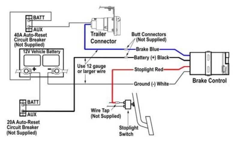
Understanding the Tekonsha trailer brake wiring diagram is crucial for anyone involved in towing, whether you're performing routine maintenance, troubleshooting electrical issues, or installing a new trailer brake controller. This guide provides a comprehensive breakdown of the diagram, its components, and practical applications, empowering you to confidently handle trailer brake wiring projects.
Purpose of the Tekonsha Trailer Brake Wiring Diagram
The Tekonsha trailer brake wiring diagram serves several vital purposes:
- Installation: It provides a clear roadmap for connecting a Tekonsha trailer brake controller to your tow vehicle's electrical system and the trailer's brake system.
- Troubleshooting: When experiencing issues with trailer brakes (e.g., no brakes, weak brakes, erratic behavior), the diagram helps you systematically trace circuits to identify faulty wiring, connections, or components.
- Repair: The diagram guides you in repairing damaged or corroded wiring, ensuring correct connections and preventing future problems.
- Understanding System Operation: Studying the diagram enhances your understanding of how the entire trailer brake system functions, from the brake controller to the trailer's electromagnets.
Key Specs and Main Parts of the System
Before diving into the diagram, let's define the key components involved in a typical Tekonsha trailer brake system:
- Trailer Brake Controller: The brain of the system, mounted inside the tow vehicle. It senses the vehicle's deceleration and applies proportional voltage to the trailer brakes. Tekonsha is a popular brand, but the principles apply to most proportional brake controllers.
- 7-Way Connector (or 4-Way): This is the standard connector that links the tow vehicle and trailer. The 7-way connector carries signals for brake lights, turn signals, running lights, reverse lights, auxiliary power (e.g., for a trailer battery), and, crucially, the trailer brake signal. A 4-way connector lacks the brake signal and auxiliary power.
- Trailer Wiring Harness: This bundle of wires runs along the trailer's frame, connecting the 7-way connector to the trailer's electrical components.
- Trailer Brake Electromagnets: Located inside the trailer's brake drums or assemblies. These electromagnets are energized by the brake controller signal, attracting them to the brake drum and actuating the brakes.
- Brake Light Switch Signal: Many proportional controllers use the brake light switch signal to initially apply the trailer brakes. This helps to provide near-instant braking force.
- Vehicle Battery: Provides power to the brake controller and, through it, to the trailer brakes.
- Ground Connections: Critically important for completing electrical circuits. Poor grounds are a common cause of trailer brake problems.
Symbols, Lines, and Colors in the Wiring Diagram
The Tekonsha trailer brake wiring diagram uses standardized symbols, lines, and colors to represent electrical components and connections. Understanding these conventions is essential for interpreting the diagram accurately.
Lines:
- Solid Lines: Indicate a direct wire connection.
- Dashed Lines: May represent a connection that is optional or located elsewhere in the vehicle's wiring system.
- Thick Lines: May indicate heavier gauge wires, often used for power and ground circuits.
Colors:
Wire colors are not universally standardized across all vehicles and trailers, but Tekonsha wiring diagrams and many common implementations follow these guidelines:
- Blue: Typically, the wire carrying the brake output signal from the brake controller to the trailer's electromagnets. This is a critical wire.
- White: Ground wire. Ensures a good electrical return path.
- Black: 12V+ Power wire. Supplies power to the brake controller from the vehicle's battery.
- Red: Brake light switch signal wire.
- Green, Yellow, Brown: Used for turn signals, running lights, and other lighting functions. These are not directly related to the trailer brake system, but are often included in the 7-way connector wiring.
Symbols:
- Resistors: Represented by a zig-zag line. In trailer brake systems, these may be used for testing or diagnostic purposes.
- Capacitors: Represented by two parallel lines. May be used for filtering electrical noise.
- Ground Symbol: Typically a triangle pointing downwards with horizontal lines beneath it. This indicates a connection to the vehicle's chassis or negative battery terminal.
- Fused Connections: Fuses are represented by a rectangular box with a wavy line inside. Fuses protect the electrical circuits from overcurrent.
Important Note: Always refer to the specific wiring diagram that comes with your Tekonsha brake controller or your trailer's documentation. While these guidelines are common, variations may exist.
How It Works: Tracing the Signal
To understand how the Tekonsha trailer brake system works, let's trace the signal flow:
- Brake Application: When the driver presses the brake pedal, the vehicle's brake light switch is activated.
- Brake Controller Activation: The brake light switch signal is sent to the Tekonsha brake controller. At the same time, an internal accelerometer in the controller detects the vehicle's deceleration rate. Proportional controllers will activate more if you brake hard.
- Signal Calculation: The brake controller calculates the appropriate voltage to send to the trailer brakes based on the vehicle's deceleration rate and the gain setting (sensitivity) of the controller.
- Signal Transmission: The brake controller sends the calculated voltage through the blue wire to the 7-way connector.
- Trailer Activation: The signal travels through the trailer's wiring harness to the brake electromagnets located inside the trailer's brake assemblies.
- Braking Force: The electromagnets are energized, creating a magnetic field that attracts the electromagnet to the brake drum. This force actuates the brake shoes, applying the trailer brakes.
- Ground Return: The electrical circuit is completed through the white ground wire, returning to the tow vehicle's chassis or negative battery terminal.
Real-World Use: Basic Troubleshooting Tips
Here are some common trailer brake problems and how the wiring diagram can help you troubleshoot them:
- No Trailer Brakes:
- Check the Fuses: Start by inspecting the fuses related to the brake controller and trailer brake circuit in both the tow vehicle and the trailer. The diagram will show the location of these fuses.
- Verify Connections: Examine all connections in the wiring harness, especially at the 7-way connector and the brake controller. Look for corrosion, loose wires, or damaged connectors. The diagram helps you identify the correct wires to inspect.
- Test the Brake Controller: Use a multimeter to check for voltage output from the brake controller when the brake pedal is pressed. If there is no output, the controller may be faulty.
- Check the Electromagnets: Disconnect the wiring at the trailer's brake drums and use a multimeter to check the resistance of the electromagnets. An open circuit (infinite resistance) indicates a faulty electromagnet.
- Weak Trailer Brakes:
- Adjust Brake Controller Gain: The brake controller's gain setting may be too low. Increase the gain until the trailer brakes are applying adequately.
- Inspect Brake Drums: Check the trailer's brake drums for wear, damage, or contamination. Worn brake shoes or drums can reduce braking performance.
- Check for Proper Grounding: A poor ground connection can significantly reduce the voltage reaching the electromagnets. Clean and tighten all ground connections.
- Erratic Trailer Brakes:
- Look for Short Circuits: Inspect the wiring harness for signs of damage or abrasion that could cause a short circuit. A short circuit can cause the brakes to apply intermittently or lock up.
- Check for Corrosion: Corrosion on the connectors or wiring can cause erratic signals. Clean all connections with a wire brush or electrical contact cleaner.
Safety Considerations
Working with electrical systems involves potential hazards. Always observe the following safety precautions:
- Disconnect the Battery: Before working on any electrical component, disconnect the negative terminal of the tow vehicle's battery to prevent accidental short circuits.
- Use Proper Tools: Use insulated tools designed for electrical work.
- Wear Safety Glasses: Protect your eyes from debris or sparks.
- Avoid Working in Wet Conditions: Moisture can increase the risk of electric shock.
- Consult a Professional: If you are unsure about any aspect of the wiring or troubleshooting process, consult a qualified mechanic or electrician.
The brake controller itself carries significant electrical current and should be handled with care. Avoid touching the terminals while the unit is powered on.
By understanding the Tekonsha trailer brake wiring diagram and following these safety guidelines, you can confidently tackle trailer brake wiring projects, ensuring safe and reliable towing.
We have a copy of a typical Tekonsha wiring diagram available for download. This diagram will provide you with a visual aid to complement this article and assist you in your troubleshooting and repair efforts.