The Complete Guide To Home Wiring Pdf Free Download
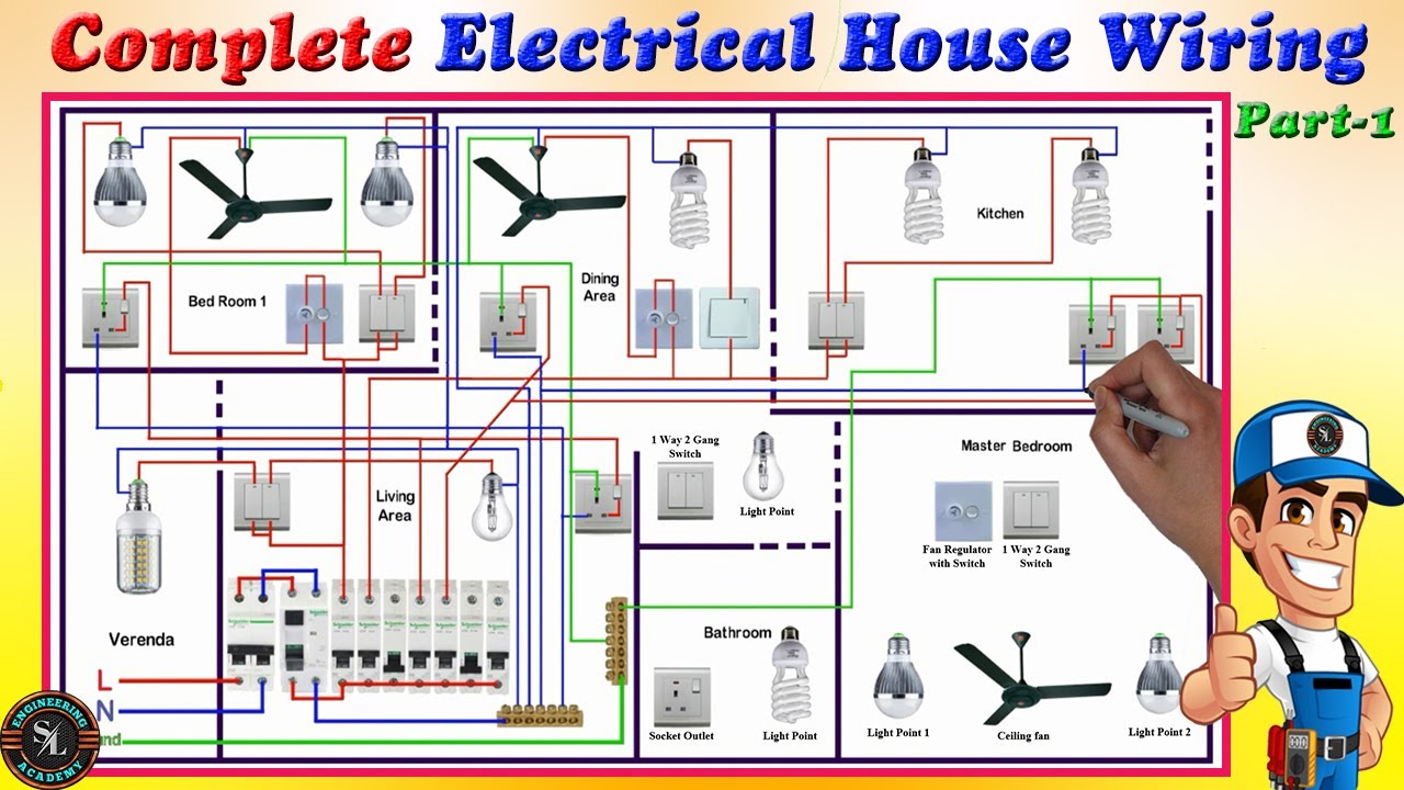
So, you're ready to tackle some home wiring, eh? That's ambitious, but with the right knowledge and precautions, it's definitely achievable. And a crucial part of that knowledge is understanding a home wiring diagram. Think of it like a blueprint for your electrical system – without it, you're essentially flying blind.
Purpose: Why This Diagram Matters
Why bother with a home wiring diagram? Several reasons jump to mind, particularly for the DIY enthusiast. First and foremost, it's invaluable for repairs. When a circuit goes dead, a diagram can quickly pinpoint the source of the problem, saving you hours of fruitless searching. Secondly, it's essential for modifications. Adding a new outlet, installing a ceiling fan, or upgrading your lighting requires understanding how your existing system is wired. Trying to do this without a diagram is a recipe for disaster – potentially dangerous and certainly frustrating. Finally, it's a fantastic learning tool. Even if you're not planning any immediate projects, studying a wiring diagram helps you understand how electricity flows through your home, making you a more informed and capable homeowner.
Key Specs and Main Parts
Before diving into the symbols, let's cover the key components you'll typically find on a home wiring diagram and their specs. Understanding these parts is critical to interpreting the diagram effectively.
Main Components:
- Service Panel (Breaker Box): This is the heart of your electrical system, where electricity enters your home and is distributed to various circuits. It contains circuit breakers (or fuses in older homes) that protect each circuit from overloads. Specs here will be things like the overall amperage rating of the panel (e.g., 100A, 200A) and the voltage (typically 120/240V in North America).
- Circuit Breakers: These devices interrupt the flow of electricity if a circuit is overloaded, preventing fires. Common ratings are 15A, 20A, and 30A. Each breaker is connected to a specific circuit.
- Wiring: Conductors that carry electricity. Common types include NM-B (non-metallic sheathed cable, often called Romex), THHN/THWN (individual wires used inside conduit), and UF (underground feeder cable). Specs are indicated by gauge (e.g., 14 AWG, 12 AWG) which determines the current-carrying capacity of the wire. Thicker wire = lower AWG number = more current.
- Outlets (Receptacles): Where you plug in your appliances and devices. Standard 120V outlets have two slots (hot and neutral) and a grounding hole. GFCI (Ground Fault Circuit Interrupter) outlets are used in wet locations like bathrooms and kitchens.
- Switches: Control the flow of electricity to lights and other devices. Single-pole switches control a light from one location, while three-way switches control a light from two locations.
- Light Fixtures: The actual light sources. The diagram will often just show a simplified symbol representing the fixture.
- Junction Boxes: Enclosures where wires are joined together. They are crucial for safety and code compliance.
Key Specifications to Look For:
- Voltage: Most household circuits are 120V, but larger appliances like stoves and dryers often use 240V.
- Amperage: The amount of electrical current a circuit can safely handle. Determined by the circuit breaker rating and the wire gauge.
- Wire Gauge (AWG): Dictates the amperage capacity of the wire. Using the wrong gauge can lead to overheating and fires.
- Circuit Type: Whether it's a general-purpose circuit, a small appliance circuit (kitchens), or a dedicated circuit (for a specific appliance).
Symbols: Decoding the Blueprint
Wiring diagrams use a standardized set of symbols to represent electrical components and connections. Learning to recognize these symbols is essential for understanding the diagram.
Lines and Connections:
- Solid Lines: Represent wires. The thickness of the line usually doesn't indicate wire gauge.
- Dotted Lines: Can represent concealed wiring, wiring in conduit, or wiring on a different plane (e.g., running behind a wall). Always check the legend on the diagram to confirm.
- Dots: Indicate a connection between wires. Where lines cross *without* a dot, it means the wires are passing each other without being connected.
Color Coding:
- Black (Hot): Carries the electrical current from the breaker to the device.
- White (Neutral): Returns the electrical current to the breaker panel, completing the circuit.
- Green or Bare Copper (Ground): Provides a safe path for electricity in case of a fault, preventing shocks.
Common Component Symbols:
- Outlets: Often represented as a circle with two lines (for the hot and neutral slots) and a half-circle below (for the ground). GFCI outlets may have a "GFCI" label or a slightly different symbol.
- Switches: Represented as a toggle switch symbol. Three-way switches have a slightly more complex symbol to indicate the two different connections.
- Light Fixtures: Typically represented as a circle with an "X" inside.
- Circuit Breaker: A square with a wavy line inside.
- Resistor: A jagged line. Represents anything that resist current flow like heating element or even a light bulb.
- Transformer: A pair of coils that are next to each other but not touching. Used to step up or down the voltage of an electrical supply.
Always refer to the legend or key on the wiring diagram, as symbols can sometimes vary slightly.
How It Works: From Source to Load
Understanding the flow of electricity is key to interpreting a wiring diagram. Electricity flows in a circuit, starting at the service panel, traveling through a circuit breaker, through the wiring (typically the black "hot" wire), to the load (e.g., a light fixture or appliance), and then returning to the service panel via the white "neutral" wire. The green or bare copper "ground" wire provides a safety path in case of a fault.
A simple circuit might look like this: Electricity flows from the breaker panel on the hot wire, to a switch. If the switch is on, the electricity continues to a light fixture, illuminating the bulb. From the light fixture, the electricity returns to the breaker panel on the neutral wire. The ground wire provides a connection to earth, so if there is a short circuit inside the light fixture the breaker will trip.
Real-World Use: Basic Troubleshooting Tips
A wiring diagram can be your best friend when troubleshooting electrical problems. Here are a few basic tips:
- Start with the obvious: Check the circuit breaker first. If it's tripped, reset it. If it trips again immediately, there's likely a short circuit.
- Identify the circuit: Use the wiring diagram to identify which circuit breaker controls the affected outlet or device.
- Isolate the problem: Unplug any devices connected to the circuit. If the problem goes away, one of those devices is faulty.
- Check connections: Loose connections are a common cause of electrical problems. Use the wiring diagram to locate junction boxes and outlets on the circuit and check the connections. Always turn off the power before opening any electrical boxes.
- Use a multimeter: A multimeter can be used to check for voltage, continuity, and resistance. This can help you pinpoint the location of a fault. Know how to use a multimeter safely before attempting any electrical testing.
Safety: Respect the Electricity
Electricity is dangerous. Always follow these safety precautions:
- Turn off the power: Before working on any electrical circuit, turn off the power at the circuit breaker. Double-check that the power is off using a non-contact voltage tester.
- Never work in wet conditions: Water conducts electricity.
- Use insulated tools: This will help protect you from shocks.
- Wear appropriate safety gear: This includes safety glasses and rubber gloves.
- Be especially careful around the service panel. This is where the full electrical service enters your home, and it can be extremely dangerous. If you're not comfortable working around the service panel, call a qualified electrician. Consider it a high-risk area.
- GFCI protection: Ensure GFCI protection in bathrooms, kitchens, and outdoor areas.
Disclaimer: Electrical work can be dangerous. This information is for educational purposes only and should not be considered a substitute for professional advice. If you are not comfortable working with electricity, consult a qualified electrician.
Ready to put this knowledge to use? We have a detailed home wiring diagram PDF file available for you to download. This resource will provide you with a visual guide to understanding the electrical system in your home. Having this diagram on hand can be incredibly helpful for various projects and repairs, enabling you to approach electrical tasks with confidence and safety.
Remember, safety is paramount when dealing with electricity. Always take the necessary precautions, and consult a professional if you're unsure about any aspect of the work. With the right tools and knowledge, you can confidently tackle many electrical projects around your home. Good luck, and stay safe!