Theft Deterrent Ignition Switch Wiring Passlock Bypass Diagram
Let's dive into the fascinating, and sometimes frustrating, world of Passlock bypass wiring. This article focuses on providing you, the experienced DIYer, with a detailed understanding of how these systems work, why you might need to bypass them, and crucially, how to do it safely. We'll be dissecting a typical theft deterrent ignition switch wiring Passlock bypass diagram, explaining each component and its function. Knowing how to read and interpret these diagrams is invaluable whether you're troubleshooting a malfunctioning system, preparing for an engine swap, or simply expanding your automotive knowledge.
Purpose: Why Bother with a Passlock Bypass Diagram?
Understanding and utilizing a Passlock bypass diagram serves several critical purposes:
- Diagnostics and Repair: Passlock systems, while intended to prevent theft, can sometimes malfunction, leaving you stranded. A diagram helps pinpoint the problem – is it the sensor, the wiring, or the Body Control Module (BCM)? This targeted approach saves time and money compared to simply replacing parts at random.
- Engine Swaps and Modifications: When swapping engines, especially into vehicles that didn't originally have a Passlock system, you might need to bypass the immobilizer function to get the engine running. The diagram is your roadmap.
- Understanding Vehicle Security Systems: Even if you don't need to bypass anything right now, learning how Passlock works gives you a deeper understanding of modern vehicle security systems. This knowledge empowers you to better protect your vehicle and troubleshoot future issues.
- Keyless Entry/Remote Start Integration: Some aftermarket remote start systems require a temporary or permanent Passlock bypass to function correctly. The diagram informs you where to tap into the system.
Key Specs and Main Parts of a Typical Passlock System
Before we delve into the diagram, let's identify the key players and their roles within a typical Passlock II or Passlock III system. Note that specific implementations may vary slightly between manufacturers and model years.
- Ignition Switch: The mechanical heart of the system. It contains the tumblers, the physical key interface, and the electrical contacts that initiate the starting process.
- Passlock Sensor: This sensor, usually located within the ignition switch housing, reads a resistance value from a resistor embedded in your key. This resistance is the core of the Passlock security.
- Wiring Harness: The network of wires connecting the components. Crucially, it includes the signal wire carrying the resistance value from the sensor to the BCM.
- Body Control Module (BCM): The "brain" of the operation. The BCM receives the resistance signal, compares it to the stored value, and determines whether to allow the engine to start. It controls the fuel injectors and starter relay based on this check.
- Powertrain Control Module (PCM)/Engine Control Module (ECM): While not directly part of the Passlock circuit, the PCM/ECM is what is being controlled by the BCM. The BCM communicates the authorization to start the engine to the PCM/ECM.
- Starter Relay: This relay receives a signal from the BCM to enable or disable the starter. This prevents the engine from cranking if the Passlock system doesn't recognize the key.
- Fuel Injectors: In some systems, the BCM will disable the fuel injectors instead of, or in addition to, the starter relay. This further ensures the engine cannot start without proper authorization.
Understanding the Diagram: Symbols, Lines, and Colors
A Passlock bypass diagram uses standard electrical symbols and color-coding to represent the various components and their connections. Here's a breakdown:
- Lines: Solid lines represent wires, indicating the flow of electricity or signals. Dashed lines may indicate shielded wires, communication buses (like CAN bus), or wires that are optional or only present in some configurations.
- Colors: Wire colors are usually abbreviated (e.g., RED, BLU, GRN, BLK, YEL). Knowing these abbreviations is essential for identifying the correct wires in the vehicle.
- Symbols:
- Resistor: A zig-zag line.
- Ground: Three horizontal lines, decreasing in length.
- Relay: A coil and a switch symbol.
- Connector: A small square or circle where wires connect to a component.
- BCM/PCM/ECM: Usually represented by a rectangle with labeled pins.
- Pin Numbers: Each wire entering a connector or module is assigned a pin number. This number is crucial for identifying the correct wire to tap into.
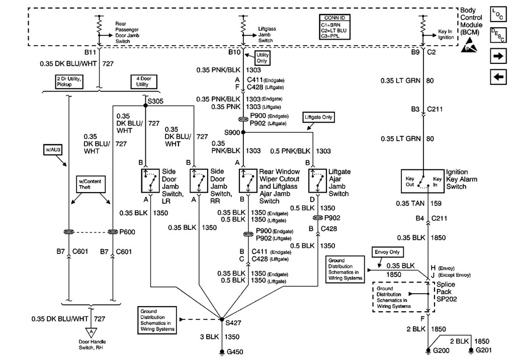
The diagram will typically show the ignition switch, the Passlock sensor integrated into it, the wiring running to the BCM, and the BCM's connections to the starter relay and/or fuel injectors. It might also include details about the resistance value expected from the key.
How a Passlock System Works: A Step-by-Step Explanation
Here's a simplified explanation of how a typical Passlock system functions:
- Key Insertion: When you insert the key into the ignition switch, the Passlock sensor reads the resistance value of the resistor embedded in the key.
- Signal Transmission: The sensor transmits this resistance value (as a voltage signal) to the BCM via a dedicated signal wire.
- Verification by BCM: The BCM compares the received resistance value with the correct value stored in its memory.
- Authorization or Denial:
- If the values match: The BCM authorizes the engine to start by activating the starter relay and allowing the fuel injectors to function.
- If the values don't match: The BCM prevents the engine from starting by deactivating the starter relay and/or disabling the fuel injectors. It may also trigger a security light on the dashboard.
A bypass typically involves tricking the BCM into thinking it's receiving the correct resistance value. This can be achieved in several ways, most commonly by either permanently installing a resistor of the correct value in place of the Passlock sensor, or using a module that learns the correct value and transmits it to the BCM each time the ignition is turned on.
Real-World Use: Basic Troubleshooting Tips
Here are a few basic troubleshooting tips when dealing with Passlock systems:
- Security Light: A flashing or solid security light on the dashboard is a common indicator of a Passlock problem.
- "No Crank" Condition: If the engine won't crank, even with a good battery, the starter relay may be disabled by the Passlock system.
- Intermittent Starting Problems: Sometimes, the Passlock system might only fail intermittently, making diagnosis more challenging.
- Check Wiring: Always start by visually inspecting the wiring harness for any signs of damage, corrosion, or loose connections. Pay particular attention to the wiring around the ignition switch and the BCM.
- Use a Multimeter: A multimeter can be used to test the voltage on the signal wire between the Passlock sensor and the BCM. You can also use it to measure the resistance of the resistor in the key (although this requires removing the resistor, which is not recommended).
Safety: Highlight Risky Components and Procedures
Working with electrical systems, especially security systems, requires caution:
- Airbag Systems: Never work on the ignition switch or surrounding wiring without disconnecting the battery and waiting at least 30 minutes to allow the airbag system capacitors to discharge. Accidental airbag deployment can cause serious injury.
- Short Circuits: Avoid creating short circuits when probing wires. Use a multimeter with a fused test lead, and be careful not to ground live wires accidentally.
- BCM Damage: Incorrectly bypassing the Passlock system can damage the BCM. Double-check all wiring connections before applying power.
- Security Implications: Remember that bypassing the Passlock system compromises your vehicle's security. Only do so when absolutely necessary, and consider alternative security measures.
We have a detailed Passlock bypass wiring diagram file available for download, complete with component locations and wiring details. This resource will be invaluable for your project.