Three Speed Fan Motor Wiring Diagram
Alright, let's dive into the wiring diagram for a three-speed fan motor. Understanding this diagram is crucial for a few reasons. First, if your fan suddenly stops working or only works on one speed, you'll need this to diagnose and repair the issue. Second, if you're upgrading or modifying your car's climate control system, knowing how the fan motor is wired will save you a lot of headaches. Finally, even just for general automotive knowledge, this is a good skill to have. We're talking about troubleshooting, upgrades, and understanding a core component of your vehicle's comfort system.
Purpose of the Wiring Diagram
The wiring diagram is essentially a roadmap of the electrical circuit that controls your fan motor. It shows you how the different components are connected, the paths the electricity takes, and the location of key parts like resistors and switches. It's indispensable for:
- Troubleshooting: Pinpointing the source of a problem (like a blown resistor or a faulty switch) by systematically checking components.
- Repairing: Replacing damaged wiring or components with the correct replacements.
- Modifying: Integrating aftermarket fan controllers or modifying the system for improved performance (e.g., adding an extra speed or a digital controller).
- Understanding: Getting a better grasp of how the entire climate control system operates.
Key Specifications and Main Parts
Before we get into the diagram itself, let's define the key components we'll be looking at:
- Fan Motor: This is the electric motor that actually spins the fan. It typically has a common (ground) wire and multiple speed wires.
- Resistor Block (or Resistor Pack): This is a series of resistors that are used to reduce the voltage applied to the fan motor, controlling its speed. Higher resistance = lower speed. The resistor block usually gets pretty hot during operation, so it’s often located in the airflow of the HVAC system to help with cooling.
- Fan Switch (or Speed Selector): This switch, usually located on your dashboard, allows you to select the desired fan speed. It routes power through different resistors (or directly to the motor) depending on the selected position.
- Power Source: This is usually the vehicle's battery, supplying the 12V (or 24V in some heavy-duty vehicles) needed to run the fan motor.
- Fuse: A safety device designed to blow (open the circuit) if there's excessive current flow, protecting the fan motor and wiring from damage. Always replace a blown fuse with one of the same amperage rating.
- Relay (Optional): In some systems, a relay is used to switch the power to the fan motor, especially if the switch is handling a lot of current. This prevents the switch contacts from burning out over time.
Symbols: Deciphering the Diagram
Understanding the symbols used in the wiring diagram is crucial. Here’s a breakdown of common symbols:
- Solid Lines: Represent wires. The thickness of the line *doesn't* necessarily indicate wire gauge, but sometimes the diagram will specify wire gauges separately.
- Dashed Lines: May represent a ground connection or, less commonly, a shielded cable. Always check the legend for the diagram to be sure.
- Circles: Often represent connections or terminals. A filled-in circle typically indicates a permanent connection.
- Rectangles: Typically represent components like resistors, relays, or fuses.
- Zigzag Lines: Represent resistors. The longer the zigzag, the higher the resistance.
- Switches: Represented by a line that can be moved to different positions, showing which circuits are connected in each position.
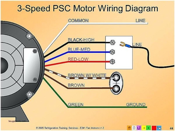
- Color Coding: Wires are often color-coded in the diagram to match the actual wires in the vehicle. Common colors include Red (power), Black (ground), and various other colors for different functions (e.g., Blue for low speed, Green for medium speed, Yellow for high speed). The diagram should have a legend indicating what each color represents.
- Ground Symbol: A series of horizontal lines decreasing in length, indicating a connection to the vehicle's chassis (ground).
Don’t forget to look for a legend on the wiring diagram. It's your key to understanding the specific symbols and abbreviations used in that particular diagram.
How It Works
The basic principle is simple: the fan switch directs power through different resistors to control the voltage applied to the fan motor. Here's how it typically works in a three-speed system:
- High Speed: When the switch is in the "High" position, power is usually sent directly to the fan motor, bypassing the resistors. This provides the full 12V (or 24V) to the motor, resulting in maximum speed.
- Medium Speed: In the "Medium" position, power is routed through one or more resistors. These resistors reduce the voltage applied to the motor, slowing it down.
- Low Speed: In the "Low" position, power is routed through a different resistor (or a combination of resistors) that offers even *more* resistance. This further reduces the voltage, resulting in the slowest fan speed.
The resistor block is a critical part of this process. It dissipates the excess energy (voltage) as heat. That's why it's important that it's properly cooled. A burnt-out resistor is a common cause of fan speed problems. When a resistor fails, often a speed will be lost entirely; for example, the fan may only work on high after a resistor for low speed fails.
Some modern systems use pulse-width modulation (PWM) to control the fan speed. In PWM systems, instead of resistors, a controller rapidly switches the power on and off. The percentage of time the power is on (the duty cycle) determines the average voltage applied to the motor, and therefore the speed. PWM systems are more efficient than resistor-based systems because they don't waste energy as heat.
Real-World Use: Basic Troubleshooting
Okay, so your fan's acting up. Here are some basic troubleshooting steps using the wiring diagram:
- No Fan Operation at All: Check the fuse first! A blown fuse is the most common cause of complete fan failure. If the fuse is good, use a multimeter to check for voltage at the fan motor connector. If there's no voltage, trace the wiring back towards the battery, checking for breaks or loose connections along the way. A bad ground can also cause this.
- Fan Only Works on High Speed: This often indicates a failed resistor in the resistor block. The high speed setting usually bypasses the resistors, so it's the only speed that will work. Inspect the resistor block for burnt or broken resistors. You can test individual resistors with a multimeter to confirm if they are working correctly.
- Fan Doesn't Work on One or More Speeds: This could also be a resistor problem or a problem with the fan switch. Use the wiring diagram to identify which resistor is used for the affected speed. Test the resistor and the switch contacts for continuity.
- Fan Runs Slowly on All Speeds: This could indicate a failing fan motor or a poor ground connection. Check the voltage at the motor connector to ensure it's receiving the correct voltage. Inspect the ground connection to ensure it's clean and tight.
Remember to always disconnect the battery before working on any electrical components. And when testing circuits, use a multimeter to avoid accidentally shorting something out.
Safety Considerations
Working with electrical components can be dangerous. Here are a few safety precautions to keep in mind:
- Disconnect the Battery: Always disconnect the negative terminal of the battery before working on any electrical components. This prevents accidental shorts and potential electrical shocks.
- Handle Capacitors with Care: Some circuits contain capacitors that can store a charge even after the power is disconnected. Discharge capacitors before working on them to avoid electrical shock.
- Use Insulated Tools: Use tools with insulated handles to protect yourself from electrical shock.
- Never Work Alone: It's always a good idea to have someone else present when working on electrical systems in case of an emergency.
- Be Aware of Hot Resistors: The resistor block can get very hot during operation. Avoid touching it immediately after the fan has been running.
High voltage components are extremely dangerous and should only be handled by qualified professionals. Incorrect wiring can result in electrical shock, fire, or damage to the vehicle's electrical system.
We have a detailed, printable PDF version of a generic three-speed fan motor wiring diagram that you can download. Remember that this is a generic diagram; always refer to the specific wiring diagram for your vehicle's make and model, which you can usually find in the vehicle's repair manual. The file includes color coding information and detailed explanations of components.