Three Wire 3 Wire Alternator Wiring Diagram
Understanding your vehicle's charging system is crucial for both routine maintenance and more complex modifications. One of the most common configurations, especially in older vehicles and aftermarket installations, is the 3-wire alternator. This article will delve into the 3-wire alternator wiring diagram, explaining its purpose, components, operation, troubleshooting, and safety considerations. We'll cover everything an experienced DIYer needs to know to confidently work with this system.
Why Understanding the 3-Wire Alternator Matters
The 3-wire alternator, while relatively simple, is the heart of your car's electrical charging system. Understanding its wiring diagram is important for several reasons:
- Repairs: Diagnosing charging issues accurately requires knowledge of the wiring. You'll be able to trace circuits, identify shorts or opens, and pinpoint the source of the problem whether it's a faulty wire, a bad connection, or an internal alternator issue.
- Upgrades and Modifications: When swapping engines, installing aftermarket electrical components (like high-powered audio systems or auxiliary lights), or upgrading your charging system, you need to ensure proper wiring and compatibility.
- Learning and Diagnostics: Understanding the principles behind the 3-wire system provides a solid foundation for understanding more complex charging systems in newer vehicles. This knowledge is valuable for diagnosing a wide range of electrical problems.
- Custom Builds: If you're building a car from scratch or heavily customizing an existing one, you'll almost certainly need to understand alternator wiring.
Key Specs and Main Parts of a 3-Wire Alternator System
The 3-wire alternator system consists primarily of the alternator itself, the battery, and the associated wiring. Here's a breakdown of the key components:
- Alternator: The primary component, responsible for converting mechanical energy from the engine into electrical energy to charge the battery and power the vehicle's electrical system. Its output is typically specified in amperes (amps) at a certain voltage (usually 12-14.5 volts).
- Battery: Provides initial power to start the engine and acts as a voltage stabilizer and reservoir for the electrical system. A typical automotive battery is a 12-volt lead-acid battery.
- Wiring: Essential for connecting the alternator to the battery and the vehicle's electrical system. Wire gauge (thickness) is critical to handle the current flow safely.
- Voltage Regulator: Crucial for maintaining a constant voltage output from the alternator. In a 3-wire alternator, the voltage regulator is typically internal. It monitors the system voltage and adjusts the alternator's field current to maintain the desired output voltage (around 14.4V is common).
- Fuses/Fusible Links: Safety devices that protect the electrical system from overcurrent conditions. They're designed to melt and break the circuit if the current exceeds a certain limit.
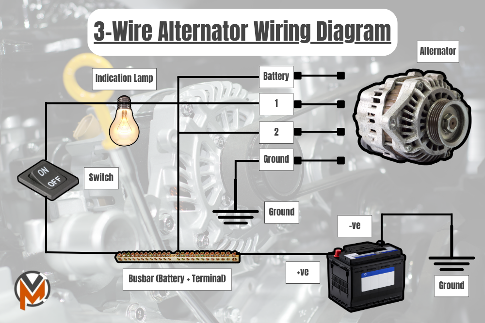
The Three Wires:
- Battery (B+) Wire: This is the main charging wire. It's a heavy-gauge wire (typically 8-gauge or thicker, depending on the alternator's output) that connects directly from the alternator's B+ terminal to the positive (+) terminal of the battery, or often to the starter solenoid's battery terminal, which is in turn connected directly to the battery. This wire carries the bulk of the charging current.
- Sense Wire: This wire, usually a smaller gauge (16-18 gauge), is connected to a point in the electrical system that represents the actual system voltage. Ideally, it's connected as far away from the alternator as possible, typically to a distribution block or the fuse box, or directly to the battery. The alternator's internal regulator uses this wire to sense the voltage at that point and adjust the alternator's output to compensate for voltage drop in the wiring. This ensures the battery receives the correct charging voltage even when there are significant loads on the system.
- Ignition/Exciter Wire: This wire, also usually a smaller gauge (16-18 gauge), provides a 12-volt switched ignition signal to the alternator when the ignition key is in the "on" or "run" position. This signal "excites" the alternator, telling it to start charging. Without this signal, the alternator will not produce any output. It is often connected to the ignition switch or to a circuit that is only energized when the ignition is on.
Understanding the Wiring Diagram Symbols
A wiring diagram uses standardized symbols to represent different electrical components and connections. Here's a brief explanation of common symbols:
- Straight Lines: Represent wires. Thicker lines usually indicate larger gauge wires.
- Dotted Lines: Sometimes used to indicate optional connections or ground wires.
- Alternator Symbol: Typically a circle with the letter "A" inside.
- Battery Symbol: Represents a battery, with "+" and "-" symbols indicating positive and negative terminals.
- Resistor Symbol: A zig-zag line.
- Fuse Symbol: A line with a break in the middle, or a rectangle with a line through it.
- Ground Symbol: Represents a connection to the vehicle's chassis, providing a path for current to return to the battery's negative terminal.
- Color Coding: Wires are often color-coded in wiring diagrams. Common colors include red (power), black (ground), and various colors for signal wires. Refer to the specific diagram for the color codes used in your vehicle.
How a 3-Wire Alternator System Works
The 3-wire alternator system operates as follows:
- When the ignition key is turned to the "on" position, the ignition/exciter wire receives 12 volts.
- This voltage energizes the alternator's internal voltage regulator.
- The voltage regulator then starts to energize the field windings inside the alternator.
- As the engine starts and the alternator begins to rotate, the rotating magnetic field induces a voltage in the stator windings.
- This voltage is rectified by diodes inside the alternator to produce a DC voltage.
- The alternator now starts producing electrical power. The B+ wire carries this power to the battery and the vehicle's electrical system.
- The voltage regulator monitors the voltage at the point where the sense wire is connected.
- If the voltage is too low (due to increased load or voltage drop in the wiring), the regulator increases the current to the field windings, which increases the alternator's output voltage.
- If the voltage is too high, the regulator reduces the current to the field windings, which decreases the alternator's output voltage.
- This closed-loop feedback system ensures that the battery receives the correct charging voltage at all times.
Real-World Use: Basic Troubleshooting Tips
Here are some basic troubleshooting tips for a 3-wire alternator system:
- No Charging: Check the ignition/exciter wire for 12 volts with the ignition on. If no voltage, trace the wire back to the ignition switch or fuse box. Also, check the B+ wire for continuity between the alternator and the battery (or starter solenoid). A blown fuse or fusible link on the B+ wire is a common cause of no charging.
- Overcharging: This is usually caused by a faulty voltage regulator. Replace the alternator. Also, check the sense wire and its connections. A poor connection on the sense wire can cause the regulator to "think" the voltage is lower than it actually is, leading to overcharging.
- Low Charging: Check the B+ wire connections for corrosion or looseness. A corroded connection can restrict current flow. Also, check the belt tension. A slipping belt can prevent the alternator from spinning at the correct speed.
- Battery Drain: A faulty diode inside the alternator can cause a battery drain when the engine is off. A simple diode test with a multimeter can often reveal this problem.
Use a multimeter to check voltages and continuity. Make sure your multimeter is set to the correct range before taking any measurements.
Safety Considerations
Working with automotive electrical systems can be dangerous. Here are some safety precautions:
- Disconnect the Battery: Always disconnect the negative (-) battery cable before working on the electrical system to prevent accidental shorts and shocks.
- Wear Safety Glasses: Protect your eyes from sparks and debris.
- Use Insulated Tools: Use tools with insulated handles to prevent electric shock.
- Be Careful with the B+ Wire: The B+ wire is always hot (connected directly to the battery). Avoid shorting it to ground.
- Proper Wire Gauges: Always use the correct wire gauge for the application. Using undersized wires can lead to overheating and fires.
- Don't work with Flammable Materials: Ensure there are no flammable materials nearby when you're working with electrical circuits.
Working on your car's electrical system can save you money and give you a better understanding of how your vehicle works. Remember, always prioritize safety and consult a qualified mechanic if you are unsure about any aspect of the repair.
We have a downloadable 3-wire alternator wiring diagram available. This detailed diagram will give you a visual guide to the connections and components discussed in this article. It is a handy reference tool for your garage.