
Throttle Body Wiring Harness Replacement
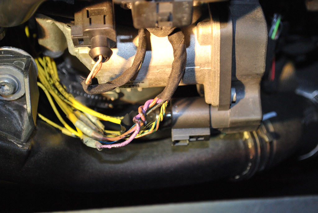
Replacing a throttle body wiring harness might seem daunting, but with a clear understanding of the system and a little know-how, it's a task many experienced DIYers can tackle. This article will delve into the intricacies of the throttle body wiring harness, explaining its purpose, components, how it functions, and how to troubleshoot common issues. Think of this as a friendly chat with your trusted mechanic, breaking down the technical jargon into easy-to-understand explanations.
Purpose and Importance
The throttle body, in essence, is the gatekeeper of air entering your engine. It controls the amount of airflow, directly impacting engine power and efficiency. The wiring harness is the critical link between the Engine Control Unit (ECU) – the car's brain – and the throttle body. This harness carries the electrical signals that tell the throttle body how much to open or close. Understanding the wiring diagram is crucial for:
- Repairs: When wires corrode, break, or become damaged, the throttle body might malfunction, leading to poor performance, rough idling, or even stalling. A wiring diagram helps pinpoint the exact faulty wire.
- Diagnosis: It allows you to trace electrical signals and identify potential short circuits or open circuits within the harness.
- Modifications: If you're upgrading to a different throttle body or performing custom wiring, the diagram is essential for ensuring correct connections.
- General Understanding: Gaining insight into how the throttle body integrates with the engine management system enhances your overall automotive knowledge.
Key Specs and Main Parts of the Throttle Body Wiring Harness
A typical throttle body wiring harness includes the following key components:
- Throttle Position Sensor (TPS): This sensor measures the throttle plate's angle and sends this information to the ECU. It usually has three wires: a 5V reference voltage, a ground, and a signal wire that outputs a voltage proportional to the throttle angle. Understanding the TPS output voltage range is critical for troubleshooting.
- Idle Air Control (IAC) Valve/Motor: This valve controls the amount of air bypassing the throttle plate when the engine is idling. This helps maintain a stable idle speed. It usually has two or four wires, depending on the design. Some newer vehicles use an electronic throttle control (ETC) system, which eliminates the IAC valve.
- Electronic Throttle Control (ETC) Motor (if equipped): Instead of a cable, an ETC system uses an electric motor to directly control the throttle plate. This allows the ECU to precisely control the throttle opening based on various inputs, such as accelerator pedal position and engine load.
- Connector(s): These are the points where the harness plugs into the ECU, the throttle body sensors (TPS and IAC), and potentially other components.
- Wires: These are the pathways for electrical signals. They are typically color-coded for identification.
- Protective Covering: This usually consists of plastic tubing or electrical tape to protect the wires from abrasion, heat, and moisture.
Understanding Wiring Diagram Symbols
Wiring diagrams use standard symbols to represent different components and connections. Here's a breakdown of some common symbols:
- Solid Lines: Represent wires. The thickness of the line doesn't necessarily indicate wire gauge.
- Dashed Lines: Often indicate shielding or grounds.
- Circles: Typically represent connectors or terminal points.
- Squares: May represent relays or other electronic components.
- Resistor Symbol (zigzag line): Indicates a resistor.
- Capacitor Symbol (parallel lines): Indicates a capacitor.
- Diode Symbol (triangle pointing to a line): Indicates a diode.
- Ground Symbol (series of descending horizontal lines): Indicates a connection to ground (the vehicle's chassis).
Color Coding: Wiring diagrams usually use color codes to identify individual wires. For example, "BLU" might represent a blue wire, "GRN" a green wire, and so on. A key or legend on the diagram will explain the color codes.
How It Works: The Signal Flow
The throttle body wiring harness acts as a communication bridge between the ECU and the throttle body itself. Here's a simplified explanation of how it works:
- The driver presses the accelerator pedal. This signal is sent to the ECU, often via an Accelerator Pedal Position (APP) sensor.
- The ECU analyzes this signal, along with other inputs such as engine speed, coolant temperature, and air intake temperature.
- Based on these inputs, the ECU determines the optimal throttle plate angle for the desired engine output.
- The ECU sends signals to the throttle body wiring harness, specifically to the ETC motor (if equipped) or the IAC valve.
- The ETC motor (if equipped) adjusts the throttle plate angle directly, or the IAC valve adjusts the amount of air bypassing the throttle plate.
- The TPS sends feedback to the ECU, confirming the throttle plate angle. This creates a closed-loop system, allowing the ECU to make precise adjustments.
Real-World Use: Basic Troubleshooting
Here are a few troubleshooting tips when dealing with throttle body wiring harness issues:
- Check Engine Light (CEL): A CEL is often the first indication of a problem. Use an OBD-II scanner to read the trouble codes. Common codes related to the throttle body include those related to the TPS, IAC valve/motor, and ETC system.
- Visual Inspection: Carefully inspect the wiring harness for any signs of damage, such as frayed wires, cracked insulation, or corroded connectors.
- Continuity Testing: Use a multimeter to check the continuity of individual wires in the harness. This will help you identify any open circuits.
- Voltage Testing: Use a multimeter to check the voltage at various points in the harness. Verify that the TPS is receiving the correct reference voltage (usually 5V).
- Resistance Testing: Check the resistance of the TPS and IAC valve/motor. Compare your readings to the manufacturer's specifications.
- Connector Cleaning: Corroded connectors can cause poor connections. Clean the connectors with electrical contact cleaner.
Safety Precautions
Working with automotive electrical systems involves inherent risks. Here are some crucial safety precautions:
- Disconnect the Battery: Always disconnect the negative battery cable before working on any electrical components. This prevents accidental short circuits and potential damage to the ECU.
- Be Careful with the ECU: The ECU is a sensitive electronic device. Avoid static electricity by grounding yourself before touching the ECU or its connectors.
- Understand Wiring Diagrams: Familiarize yourself with the wiring diagram before attempting any repairs. Incorrect wiring can damage the ECU or other components.
- Use Proper Tools: Use high-quality electrical tools, such as a multimeter, wire strippers, and crimpers.
- Insulate Connections: After making any wire repairs, ensure that the connections are properly insulated to prevent short circuits. Use heat shrink tubing or electrical tape.
- High Voltage Components: Be extremely cautious around components involved in the ignition system (spark plugs, ignition coils). These components carry high voltage and can deliver a dangerous shock. The throttle body wiring is usually low voltage DC, but it's still important to be cautious.
Remember, proper diagnosis and careful execution are key to a successful throttle body wiring harness replacement or repair. If you're unsure about any aspect of the process, it's always best to consult with a qualified mechanic.
We have a detailed throttle body wiring diagram file available for download. This resource will provide specific wiring information for various vehicle makes and models, aiding in accurate diagnosis and repair. This diagram will be invaluable for completing this project. We believe in empowering our readers with the right resources to tackle such projects successfully.