
Throttle Position Sensor Wiring Diagram
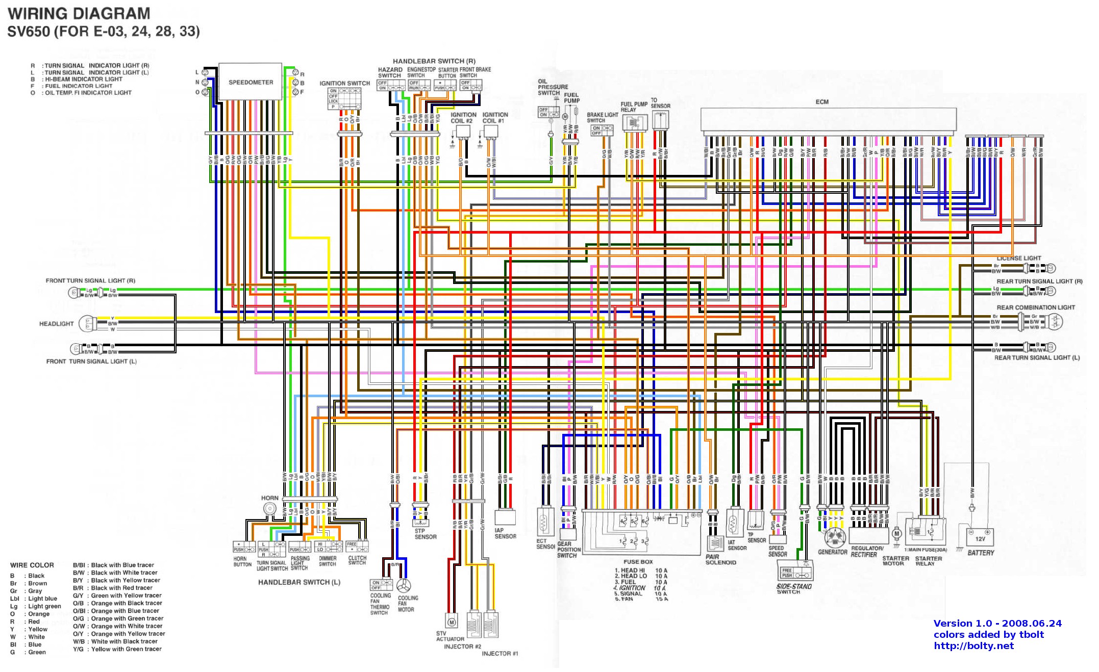
Understanding your vehicle's Throttle Position Sensor (TPS) wiring diagram is crucial for various automotive tasks, from basic repairs to more advanced modifications. This isn't just about blindly replacing parts; it's about diagnosing problems accurately and ensuring your car runs optimally. Whether you're dealing with a surging idle, poor fuel economy, or a check engine light, a solid understanding of the TPS circuit is invaluable.
Why Bother With the TPS Wiring Diagram?
A TPS wiring diagram provides a visual representation of the electrical connections within the TPS circuit. This knowledge is vital for:
- Troubleshooting Electrical Issues: Pinpointing breaks, shorts, or open circuits within the TPS wiring.
- Performing Repairs: Accurately identifying and replacing damaged wiring or connectors.
- Making Modifications: Integrating aftermarket components, such as a new throttle body, or custom engine management systems.
- Understanding Engine Management: Gaining a deeper understanding of how the Engine Control Unit (ECU) uses TPS data.
- Avoiding Costly Shop Visits: Potentially diagnosing and fixing problems yourself, saving time and money.
Key Specs and Main Parts of the TPS Circuit
The TPS circuit typically consists of the following key components:
- Throttle Position Sensor (TPS): A potentiometer (a variable resistor) mounted on the throttle body that measures the throttle plate angle. As the throttle plate moves, the TPS outputs a varying voltage signal to the ECU.
- Engine Control Unit (ECU): The brain of the engine management system. It receives the TPS signal, along with other sensor inputs, and uses this information to control fuel injection, ignition timing, and other engine parameters.
- Wiring Harness: The network of wires that connects the TPS to the ECU and other components. This includes individual wires, connectors, and splices.
- Connectors: These are the physical interfaces that allow you to connect and disconnect the TPS from the wiring harness. They're prone to corrosion and damage, making them a frequent source of problems.
- Voltage Supply: The TPS typically receives a regulated 5-volt reference signal from the ECU.
- Ground: The TPS also needs a solid ground connection to function correctly.
The TPS itself usually has three pins:
- Voltage Reference (VREF): Typically 5 volts, supplied by the ECU.
- Ground (GND): Provides a return path for the current.
- Signal (SIG): The variable voltage signal sent to the ECU, representing the throttle plate angle.
Decoding TPS Wiring Diagram Symbols
Wiring diagrams use standard symbols to represent electrical components and connections. Understanding these symbols is crucial for interpreting the diagram effectively.
- Solid Lines: Represent wires. Thicker lines may indicate heavier gauge wiring.
- Dashed Lines: Often indicate shielding or connections on the back side of a component.
- Colors: Each wire is typically identified by a color code (e.g., Red/White, Blue/Yellow). These colors are standardized and help trace wires throughout the harness.
- Circles with Numbers: Represent connectors. The number indicates the pin number within the connector.
- Ground Symbols: Various symbols are used to represent ground connections, often resembling a rake or a series of downward-pointing lines.
- Resistor Symbol: A zig-zag line, representing a resistor or in this case, the variable resistance inside the TPS.
- Capacitor Symbol: Two parallel lines, representing a capacitor. (Rarely present directly in the TPS circuit, but common in the ECU).
- ECU Symbol: Often a rectangle or square with labeled pins, representing the Engine Control Unit.
- Splice Symbol: Usually a dot where wires intersect, indicating a connection.
Colors are extremely important! Common colors include (but are not limited to):
- Red: Usually indicates power or voltage supply.
- Black: Typically represents ground.
- White: Can represent a signal wire.
- Blue, Green, Yellow: Often used for various signal wires.
Always refer to the specific wiring diagram for your vehicle's year, make, and model, as color codes and component locations can vary significantly.
How the TPS Circuit Works
The TPS circuit is relatively straightforward in principle. The ECU sends a 5-volt reference voltage (VREF) to the TPS. The TPS acts as a voltage divider, with the throttle plate angle determining the resistance value. As the throttle plate opens, the resistance changes, causing the voltage signal (SIG) sent back to the ECU to increase. The ECU interprets this voltage signal as the throttle position. At closed throttle, the signal voltage is typically around 0.5 volts. At wide-open throttle (WOT), the signal voltage should be close to 4.5 volts.
The ECU uses this throttle position information for a variety of functions, including:
- Fuel Injection: Increasing fuel delivery as the throttle opens to meet the increased air demand.
- Ignition Timing: Adjusting ignition timing for optimal performance and emissions.
- Idle Speed Control: Maintaining a stable idle speed by adjusting the throttle position or idle air control valve (IAC).
- Transmission Control: Some automatic transmissions use TPS data for shift scheduling.
A faulty TPS or wiring can disrupt these functions, leading to poor engine performance, drivability issues, and diagnostic trouble codes (DTCs).
Real-World Use: Basic Troubleshooting Tips
Here are some basic troubleshooting tips using the TPS wiring diagram:
- Check for Voltage: Use a multimeter to verify that the TPS is receiving the correct voltage reference (typically 5 volts). Disconnect the connector and measure between the VREF and GND pins.
- Check for Ground: Verify that the TPS has a good ground connection. Use a multimeter to measure resistance between the GND pin and a known good ground point on the vehicle's chassis. Resistance should be very low (close to 0 ohms).
- Check the Signal Wire: With the TPS connected, use a multimeter to measure the voltage on the signal (SIG) wire. The voltage should change smoothly and linearly as you open and close the throttle. Look for any sudden jumps, dead spots, or erratic behavior.
- Inspect Connectors and Wiring: Carefully inspect the TPS connector and wiring for corrosion, damage, or loose connections. Clean corroded contacts with electrical contact cleaner. Repair or replace damaged wiring as needed.
- Scan for Diagnostic Trouble Codes (DTCs): Use an OBD-II scanner to check for any TPS-related DTCs. Common codes include P0120, P0121, P0122, and P0123. These codes can provide valuable clues about the nature of the problem.
- Perform a TPS Reset/Relearn: Some vehicles require a TPS reset or relearn procedure after replacing the TPS. This allows the ECU to properly calibrate the new sensor. Refer to your vehicle's service manual for specific instructions.
Always double-check your findings against the wiring diagram to ensure you're testing the correct wires and connections.
Safety Considerations
Working with automotive electrical systems can be dangerous. Here are some safety precautions to keep in mind:
- Disconnect the Battery: Before working on any electrical circuit, disconnect the negative battery cable to prevent accidental shorts and electrical shocks.
- Avoid Working on Live Circuits: Whenever possible, avoid working on circuits with the ignition on. This reduces the risk of electrical shock and damage to components.
- Use Proper Tools: Use properly insulated tools and test equipment.
- Be Careful Around the Throttle Body: The throttle body can contain moving parts. Be careful not to get your fingers caught in the throttle linkage.
- Be Aware of the Fuel System: The fuel system is under pressure. Avoid disconnecting fuel lines or working near fuel leaks.
- High Energy Ignition Systems: Be extremely careful around ignition coils and spark plug wires, as they can deliver a high-voltage shock even with the battery disconnected.
If you are not comfortable working on automotive electrical systems, it is best to consult a qualified mechanic.
Conclusion
Understanding the Throttle Position Sensor (TPS) wiring diagram is a valuable skill for any car enthusiast or DIY mechanic. By understanding the circuit's components, symbols, and operation, you can effectively troubleshoot electrical issues, perform repairs, and gain a deeper understanding of your vehicle's engine management system. Remember to always consult the specific wiring diagram for your vehicle and to prioritize safety when working on electrical systems. With the knowledge you've gained here, you're well-equipped to tackle TPS-related issues with confidence.
We have a detailed TPS wiring diagram file available for download. It includes a breakdown of common wiring configurations, color codes, and troubleshooting tips. Contact us for access.