
Toyota 3 Pin Alternator Wiring Diagram
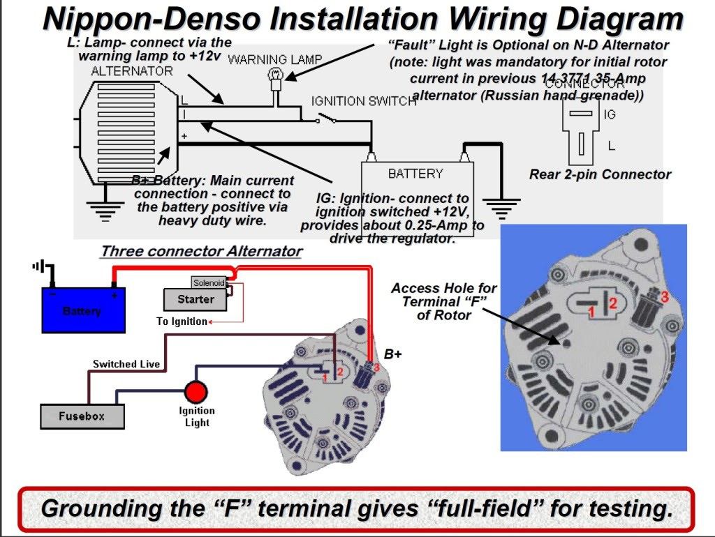
Understanding the wiring of your vehicle's charging system is crucial for maintaining its reliability and longevity. The Toyota 3-pin alternator is a common configuration found in many models, and grasping its wiring diagram can empower you to perform basic repairs, diagnose issues, and even undertake some performance modifications with confidence. This article will provide a detailed breakdown of the Toyota 3-pin alternator wiring diagram, geared towards experienced DIYers like yourself.
Purpose of Understanding the Wiring Diagram
Why delve into this wiring diagram? The reasons are plentiful:
- Troubleshooting Charging Issues: A faulty alternator can lead to a dead battery and a stranded vehicle. Understanding the wiring allows you to pinpoint whether the alternator itself, the wiring, or the battery is the culprit.
- Performing Repairs: Replacing a damaged connector or wire requires knowing where each wire connects and its function.
- Learning Automotive Electrical Systems: The alternator is a key component of the charging system. Understanding it provides a solid foundation for comprehending broader automotive electrical principles.
- Customization and Modifications: If you're upgrading your audio system or adding auxiliary lights, you may need to tap into the charging system. A solid understanding of the alternator wiring prevents damaging your vehicle's electrical system.
- Verification After Repairs: After any repair involving the alternator or related wiring, the diagram allows you to verify that everything is correctly connected.
Key Specs and Main Parts of a 3-Pin Alternator System
Before diving into the diagram itself, let's define the key components and specifications commonly associated with a Toyota 3-pin alternator:
- Alternator: The device responsible for generating electrical power to recharge the battery and power the vehicle's electrical loads (lights, radio, etc.) while the engine is running.
- Battery: Stores electrical energy and provides power to start the engine and operate electrical components when the engine is off.
- Voltage Regulator: A critical component (often integrated into the alternator on modern vehicles) that maintains a consistent output voltage (typically around 13.8-14.4 volts) from the alternator, preventing overcharging and damage to the battery and other electrical components.
- Wiring Harness: A collection of wires bundled together to connect the alternator to the vehicle's electrical system.
- Connectors: Plastic housings that provide secure and reliable electrical connections between the alternator, wiring harness, and other components. The 3-pin connector is the focus of this article.
- Fuse Box: Contains fuses that protect circuits from overcurrent. An alternator circuit typically has a large fuse (e.g., 80A-120A).
The 3-pin connector on the alternator typically has the following pins:
- B+ (Battery Positive): This is the main output terminal that connects directly to the positive (+) terminal of the battery, usually through a fusible link or high-amp fuse. This wire carries the charging current. It's typically a thick gauge wire (e.g., 4-8 AWG).
- IG (Ignition): This terminal receives a 12V signal from the ignition switch when the engine is running. This signal activates the voltage regulator and tells the alternator to start charging. This is typically a smaller gauge wire (e.g., 16-18 AWG).
- L (Lamp/Charge Indicator): This terminal connects to the charge indicator lamp (usually a battery symbol) on the instrument cluster. When the ignition is on and the engine is not running, this terminal is grounded through the bulb, completing the circuit and illuminating the lamp. Once the alternator starts charging, it provides a positive voltage to this terminal, which turns off the lamp. This wire also provides feedback to the Engine Control Unit (ECU) in some vehicles.
Symbols, Lines, Colors, and Icons in the Wiring Diagram
Understanding the symbols used in the wiring diagram is essential for interpreting it correctly. Here's a breakdown:
- Solid Lines: Represent wires. The thickness of the line *may* indicate the wire gauge (thicker lines generally representing larger gauge wires capable of carrying more current), but this is not always consistent and should be confirmed with wire markings or specifications.
- Dotted Lines: Can represent shielded wires or connections that are not always present depending on the vehicle model or options.
- Color Codes: Wires are color-coded to help identify them. Common Toyota color codes include:
- W (White): Often used for ground or signal wires.
- B (Black): Typically indicates ground.
- R (Red): Usually used for battery power or other constant power sources.
- Y (Yellow): Can be used for various circuits.
- G (Green): Often used for signal wires.
- L (Blue): Can be used for various circuits.
- Connector Symbols: Represent electrical connectors. They often have numbers indicating the pin assignments.
- Ground Symbol: Usually a series of horizontal lines or a triangle pointing downwards, indicating a connection to the vehicle's chassis ground.
- Fuse Symbol: A zigzag line inside a rectangle, indicating a fuse. The fuse rating (in Amperes) is usually indicated near the symbol.
- Relay Symbol: A coil with a switch. Relays are used to control high-current circuits with a low-current signal.
- Alternator Symbol: Typically a circle with the letter "A" inside or a simplified representation of the alternator's internal components.
How It Works: The Charging Circuit Explained
Here's how the Toyota 3-pin alternator charging circuit functions:
- Ignition On: When the ignition switch is turned to the "ON" position, a 12V signal is sent to the IG terminal of the alternator. This energizes the voltage regulator within the alternator. The charge indicator lamp in the instrument cluster also receives power through the ignition switch and is grounded through the L terminal of the alternator (because the alternator is not yet charging). This ground connection illuminates the lamp.
- Engine Starting: When the engine starts, the crankshaft drives the alternator through a belt.
- Alternator Generating Power: As the alternator rotates, it generates alternating current (AC). This AC current is converted to direct current (DC) by internal diodes.
- Voltage Regulation: The voltage regulator monitors the output voltage of the alternator and adjusts the field current (the current supplied to the alternator's rotor) to maintain a stable output voltage (around 13.8-14.4 volts). This prevents overcharging the battery and damaging electrical components.
- Charging the Battery: The DC voltage produced by the alternator is sent to the battery through the B+ terminal. This current recharges the battery and provides power to the vehicle's electrical system.
- Charge Indicator Lamp Off: Once the alternator is charging, it provides a positive voltage to the L terminal. This positive voltage cancels out the ground connection that was illuminating the charge indicator lamp, causing the lamp to turn off.
Real-World Use: Basic Troubleshooting Tips
Here are some common issues and troubleshooting tips related to the 3-pin alternator wiring:
- Charge Indicator Lamp Stays On: This often indicates a problem with the alternator itself, the voltage regulator, or the wiring between the alternator and the instrument cluster. Check the L terminal wire for breaks or shorts. Also, verify that the alternator is actually producing voltage.
- No Charging: If the battery is not charging and the voltage across the battery terminals remains low (around 12V or less) with the engine running, check the following:
- B+ Terminal: Ensure the B+ terminal is securely connected to the battery positive terminal and that the wire is not damaged. Check the fuse or fusible link in the B+ circuit.
- IG Terminal: Verify that the IG terminal receives 12V when the ignition is on. If not, check the ignition switch and the wiring between the switch and the alternator.
- Alternator Output Voltage: Use a multimeter to measure the voltage at the B+ terminal with the engine running. It should be between 13.8 and 14.4 volts. If it's significantly lower or higher, the alternator or voltage regulator may be faulty.
- Ground Connection: Ensure the alternator is properly grounded to the engine block or chassis. A poor ground connection can cause charging problems.
- Overcharging: If the battery is constantly being overcharged (evident by a boiling battery or frequent battery failures), the voltage regulator is likely faulty.
- Intermittent Charging: Loose connections or corroded terminals can cause intermittent charging problems. Inspect all connections and clean them thoroughly.
Safety Precautions
Working with automotive electrical systems can be dangerous. Always take the following precautions:
- Disconnect the Battery: Before working on any electrical component, disconnect the negative (-) terminal of the battery to prevent short circuits and electrical shocks.
- Avoid Short Circuits: Be careful not to short circuit any wires to the vehicle's chassis. This can damage electrical components and start a fire.
- Use Proper Tools: Use insulated tools to prevent electrical shocks.
- Work in a Well-Ventilated Area: Batteries can produce hydrogen gas, which is flammable. Work in a well-ventilated area to prevent explosions.
- Fusible Link/High Amp Fuse: The B+ wire often has a fusible link or high-amp fuse. This is a *critical* safety component. Never bypass it. If it blows, diagnose the cause before replacing it with a fuse of the correct rating. Bypassing this can lead to a fire if there is a short.
By understanding the Toyota 3-pin alternator wiring diagram and following these guidelines, you'll be well-equipped to diagnose and repair charging system problems, saving you time and money. Remember, if you're unsure about any procedure, consult a qualified mechanic.
We have a detailed wiring diagram file available for download. Please reach out via the contact form on our website to request access.