Toyota 4 Pin Alternator Wiring Diagram
So, you're diving into the world of Toyota alternator wiring, specifically the 4-pin variety? Excellent! This is a common configuration, and understanding its wiring diagram is crucial for troubleshooting charging issues, performing alternator upgrades, or even integrating an alternator into a custom build. This article will provide a clear, technically accurate, yet approachable explanation of the Toyota 4-pin alternator wiring diagram.
Purpose of Understanding the Wiring Diagram
Why bother with the diagram? Several reasons stand out:
- Troubleshooting Charging Issues: When your battery isn't charging correctly, the alternator is a prime suspect. The wiring diagram helps you pinpoint breaks, shorts, or voltage drops in the circuit.
- Alternator Replacement/Upgrades: Replacing an alternator with a different amperage rating (higher output) sometimes requires modifying the wiring to handle the increased current. The diagram shows you what needs modification.
- Custom Car Builds/Engine Swaps: Integrating a Toyota engine (and its associated electrical system) into a non-Toyota chassis requires knowing exactly where each wire goes.
- Diagnostic Understanding: Knowing how the charging system works allows you to interpret scan tool data and diagnose problems more effectively.
Key Specs and Main Parts of a Toyota 4-Pin Alternator
Before we dive into the diagram itself, let's identify the key components and their roles:
- Alternator: The heart of the charging system. It converts mechanical energy from the engine into electrical energy to power the car's electrical components and charge the battery.
- Voltage Regulator: This crucial component maintains a consistent voltage output from the alternator, preventing overcharging and damage to sensitive electronics. In most modern Toyota 4-pin alternators, the voltage regulator is internal.
- Battery: Stores electrical energy and provides power to start the engine and operate electrical components when the engine isn't running.
- Battery Cables: Heavy-gauge cables connecting the battery to the chassis ground and the alternator. These carry high currents and must be in good condition.
- Wiring Harness: A collection of wires bundled together to connect various components. Specific to the alternator, these wires connect the alternator to the battery, ignition switch, and engine control unit (ECU).
- Fuses/Fusible Links: Safety devices that protect the electrical system from overcurrents. A blown fuse indicates a short circuit or excessive current draw.
Regarding specifications, pay attention to the following:
- Alternator Amperage Rating: Indicates the maximum current the alternator can produce. This is typically stamped on the alternator's housing.
- Voltage: Typically 12V or 24V, depending on the vehicle.
- Wiring Gauge: The thickness of the wires. Higher amperage alternators require thicker wires to handle the increased current.
Understanding the Symbols in a Toyota 4-Pin Alternator Wiring Diagram
Wiring diagrams use standardized symbols to represent electrical components and connections. Understanding these symbols is essential for interpreting the diagram.
- Solid Lines: Represent wires. Thicker lines typically indicate wires that carry higher current.
- Dotted Lines: May represent shielded wires or wires that are not directly part of the core alternator circuit but are related to its control.
- Circles: Often represent connections or terminals.
- Rectangles: Can represent various components, such as the voltage regulator or a diode.
- Zigzag Lines: Represent resistors.
- Ground Symbol: Indicates a connection to the vehicle's chassis ground. This is typically a series of horizontal lines, with the bottom line being the longest.
- Battery Symbol: Represents the battery. It consists of alternating long and short parallel lines, with a "+" and "-" sign indicating the positive and negative terminals.
- Fusible Link Symbol: Typically a squiggly line enclosed in a teardrop shape.
Color Coding: Wiring diagrams often use color codes to identify different wires. While Toyota's specific color coding can vary slightly depending on the model year and vehicle, some common colors and their functions are:
- White (W): Often used for ground connections.
- Red (R): Usually indicates a power wire from the battery.
- Blue (L): Often used for the alternator indicator light circuit.
- Yellow (Y): May be used for ignition or sensor signals.
- Black (B): Always ground.
Important: Always refer to the specific wiring diagram for your vehicle's year, make, and model to ensure accurate identification of wire colors and their functions.
How the Toyota 4-Pin Alternator Charging System Works
Here’s a simplified explanation of how the charging system functions, using the 4-pin alternator:
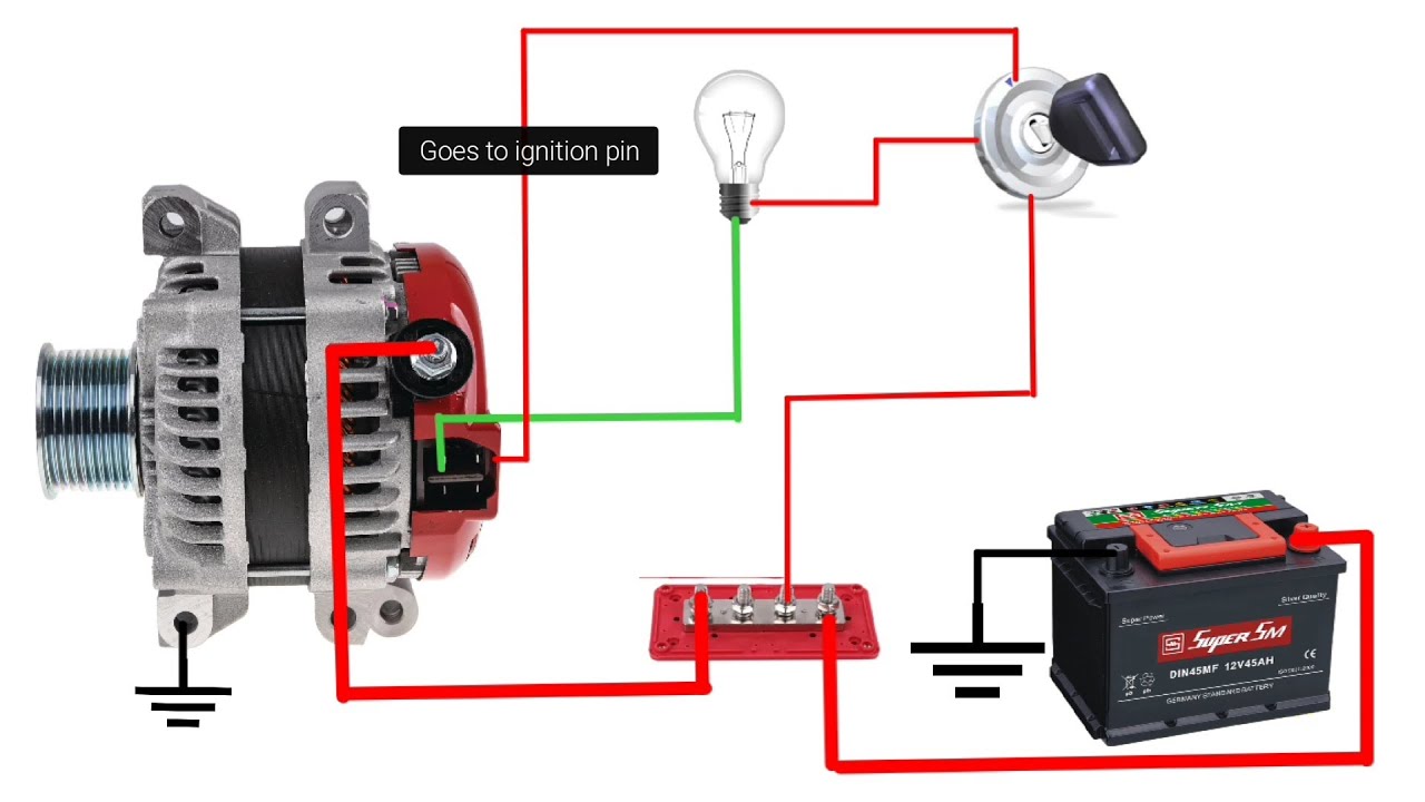
- Battery Voltage Supply: One pin is usually a direct connection to the battery positive (+) terminal. This provides the alternator with the voltage it needs to start producing power. This is typically a heavy gauge wire due to the high current flow.
- Ignition Sense (IG): This pin receives voltage when the ignition switch is turned to the "ON" position. This signal tells the alternator to begin charging the battery and powering the vehicle's electrical system. This is usually a smaller gauge wire.
- Lamp Circuit (L or ALT): This pin is connected to the charge warning lamp on the instrument cluster. When the alternator isn't charging properly, the lamp lights up. This circuit also plays a role in initially exciting the alternator to start charging. The ECU often monitors this line for alternator performance.
- Field Control (FR): This pin allows the ECU to monitor and, in some cases, control the alternator's output. The ECU uses this information to adjust the engine's idle speed or to reduce the electrical load on the engine during high-demand situations (e.g., sudden acceleration).
The voltage regulator, internal to the alternator, constantly monitors the battery voltage and adjusts the alternator's output to maintain a consistent voltage level, typically around 13.8-14.4 volts. This prevents overcharging or undercharging the battery.
Real-World Use: Basic Troubleshooting Tips
Here are some basic troubleshooting tips you can use with the wiring diagram:
- No Charge Warning Light: If the charge warning light doesn't come on when the ignition is turned on, check the bulb and the wiring to the "L" terminal on the alternator.
- Continuously Lit Charge Warning Light: If the charge warning light stays on while the engine is running, it indicates a charging system problem. Check the alternator's output voltage and the condition of the battery.
- Low Voltage: Use a multimeter to measure the voltage at the battery terminals with the engine running. It should be between 13.8 and 14.4 volts. If it's lower, the alternator may be faulty, or there may be a wiring problem.
- High Voltage: A voltage reading above 14.4 volts indicates a potential problem with the voltage regulator.
- Voltage Drops: Use a multimeter to measure voltage drops across wiring connections. Excessive voltage drops indicate corrosion or loose connections.
Safety Considerations
Working with automotive electrical systems can be dangerous. Here are some safety precautions to keep in mind:
- Disconnect the Battery: Always disconnect the negative (-) battery terminal before working on the electrical system. This prevents accidental shorts and electrical shocks.
- Use Proper Tools: Use insulated tools and wear safety glasses to protect yourself from electrical hazards.
- Work in a Well-Ventilated Area: Batteries can release explosive gases. Work in a well-ventilated area and avoid sparks or open flames.
- Be Careful with High-Current Components: The alternator, battery cables, and starter motor carry high currents. Avoid touching these components while the engine is running.
- The battery and alternator can supply high current and are extremely dangerous to short.
This article has provided a comprehensive overview of the Toyota 4-pin alternator wiring diagram. Remember, always consult the specific wiring diagram for your vehicle's year, make, and model. With this knowledge and the right tools, you can confidently diagnose and repair charging system problems.
We have a sample Toyota 4-Pin Alternator Wiring Diagram file available for download. This will provide a visual aid to complement the information discussed in this article. You can access it by contacting us.