
Toyota 4 Wire Alternator Wiring Diagram
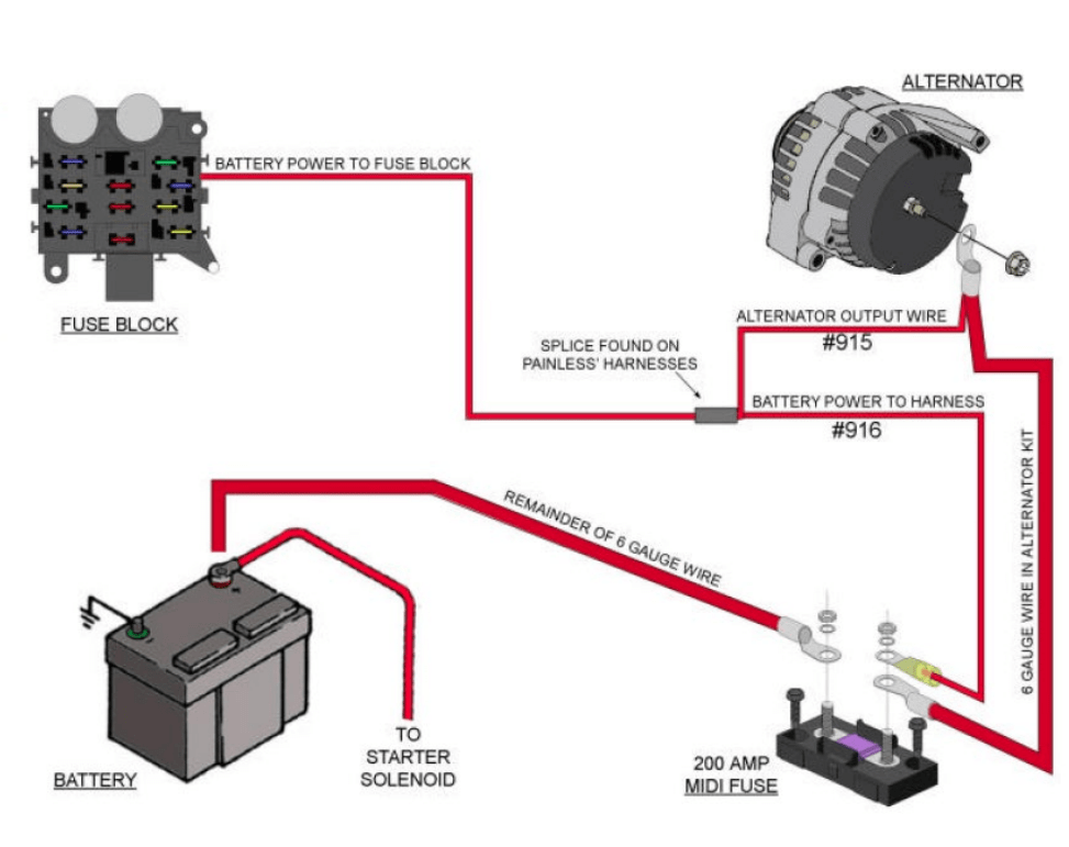
Understanding your Toyota's alternator wiring, particularly the 4-wire configuration, is crucial for anyone tackling electrical repairs, modifications, or even just wanting a deeper understanding of their vehicle. This guide provides a comprehensive breakdown of the Toyota 4-wire alternator wiring diagram, empowering you with the knowledge to diagnose issues, perform repairs, and confidently handle aftermarket installations.
Purpose of Understanding the Wiring Diagram
Why bother learning about this diagram? Simple: it's your roadmap to the alternator's electrical system. It allows you to:
- Diagnose charging problems: Is your battery not charging? The diagram helps you pinpoint the source of the issue, whether it's a faulty wire, a bad connection, or a failing component.
- Perform alternator replacements correctly: Ensuring proper wiring is essential for the new alternator to function correctly and avoid damaging other electrical components.
- Understand aftermarket upgrades: Installing aftermarket accessories, such as larger batteries or high-powered audio systems, often requires modifying the charging system. The diagram helps you do so safely and effectively.
- Gain a deeper understanding of automotive electrical systems: Learning the basics here provides a foundation for tackling more complex electrical tasks in the future.
Key Specs and Main Parts of a Toyota 4-Wire Alternator System
The Toyota 4-wire alternator system, while seemingly simple, plays a vital role in maintaining your car's electrical health. Here's a breakdown of the key components and their specifications:
Alternator Components
- Stator: The stationary part of the alternator that contains the windings where electricity is generated.
- Rotor (or Armature): The rotating part inside the stator, creating a magnetic field.
- Voltage Regulator: This critical component controls the alternator's output voltage, preventing overcharging and damage to the battery and other electrical components. In a 4-wire system, the regulator often relies on external sensing.
- Rectifier (Diode Bridge): Converts the AC voltage generated by the alternator into DC voltage suitable for charging the battery and powering the vehicle's electrical system.
- Brushes: Conduct electricity to the rotor, enabling the creation of the magnetic field.
- Pulley: Driven by the engine's crankshaft via a belt, causing the rotor to spin.
The Four Wires Explained
Each wire in the 4-wire system has a specific function:
- Battery (B+) Terminal: This thick gauge wire connects directly to the positive terminal of the battery. It carries the high-current output of the alternator to charge the battery and supply power to the vehicle's electrical system. Think of it as the main power output.
- Ignition (IG) Terminal: This wire receives power when the ignition switch is turned on. It signals the alternator to start operating. This is an input that essentially tells the alternator, "Hey, the engine is running, start charging!".
- Sense (S) Terminal: This wire is the voltage sensing wire. It's usually connected to the battery positive terminal or a nearby distribution point. The voltage regulator uses the voltage reading from this wire to compensate the output. This allows the alternator to adjust its output to overcome voltage drops in the system and provide a consistent charging voltage at the battery.
- Lamp (L) Terminal: This wire connects to the charge warning lamp (battery light) on the instrument cluster. When the ignition is on and the alternator isn't charging, this wire provides a ground, illuminating the lamp. Once the alternator starts charging, it provides a voltage on this wire, turning the lamp off. It is an output, used to monitor charging performance.
Understanding Symbols in the Wiring Diagram
Wiring diagrams use standardized symbols to represent components and connections. Here's a breakdown of common symbols you'll encounter:
- Straight Lines: Represent wires. Thicker lines usually indicate larger gauge wires, carrying more current (like the B+ wire).
- Dotted Lines: May indicate shielded wires or wires that are part of a harness.
- Circles: Can represent connectors or terminals.
- Resistors: Zigzag lines, indicating resistance to current flow.
- Diodes: Triangle pointing to a vertical line, indicating current flow in one direction only.
- Ground Symbol: Typically a series of horizontal lines decreasing in size, indicating a connection to the vehicle's chassis (ground).
- Color Codes: Wires are often color-coded (e.g., Red for positive, Black for ground). The wiring diagram will usually include a legend indicating the color of each wire. Always verify wire colors with your specific vehicle’s wiring harness!
How It Works: The Alternator's Operation
Here's a simplified explanation of how the alternator and its wiring work together:
- When the ignition is turned on, the IG terminal receives power, priming the alternator.
- The engine starts, and the belt drives the alternator pulley, spinning the rotor.
- As the rotor spins, it creates a magnetic field.
- This magnetic field induces an alternating current (AC) in the stator windings.
- The rectifier converts the AC voltage to DC voltage.
- The voltage regulator monitors the voltage at the S terminal (sense wire).
- Based on the voltage at the S terminal, the voltage regulator adjusts the amount of current supplied to the rotor. This controls the strength of the magnetic field and, therefore, the alternator's output voltage.
- The alternator outputs DC voltage through the B+ terminal, charging the battery and powering the vehicle's electrical system.
- If the alternator fails to charge, the L terminal provides a ground, illuminating the battery warning light on the dashboard.
Real-World Use: Basic Troubleshooting Tips
Using the wiring diagram, you can diagnose common charging problems. Here are a few scenarios:
- Battery light is on: Check the L terminal wire and its connections. A broken or loose connection can cause the light to illuminate even if the alternator is charging. Verify that the alternator is outputting the correct voltage (typically 13.5-14.5 volts) at the B+ terminal. If the voltage is low or non-existent, the alternator may be faulty.
- Battery not charging: Check the B+ terminal wire and its connections. A loose or corroded connection can prevent the battery from charging. Verify the fuse for the charging system is good. Use a multimeter to check the voltage at the B+ terminal while the engine is running. If it's significantly lower than battery voltage, the alternator may be the issue. Also, check the belt tension.
- Overcharging: If the voltage at the battery is consistently above 15 volts, the voltage regulator is likely faulty. This can damage the battery and other electrical components. You can use a multimeter to check the voltage reading from the S-terminal, and compare it with the voltage reading from the B+ terminal, if these values are too different from each other, the S-terminal is probably the source.
- Engine Stalling: A faulty alternator could put an excessive amount of load on the engine leading to stalling. Test voltage output and check the regulator as previously mentioned.
Remember to always disconnect the negative battery terminal before working on the electrical system.
Safety Precautions
Working with automotive electrical systems can be dangerous. Here are some crucial safety precautions:
- Disconnect the Battery: Always disconnect the negative battery terminal before working on the electrical system. This prevents accidental shorts and potential shocks.
- High Current: The B+ terminal carries a large amount of current. Avoid touching it with metal tools while the battery is connected.
- Proper Tools: Use insulated tools designed for automotive electrical work.
- Read the Diagram: Study the wiring diagram carefully before starting any work.
- Fuses: Never bypass fuses. Replace them with the correct amperage rating.
Important note: The voltage regulator is a critical component. Replacing it with an incompatible unit can lead to serious electrical damage. If you're unsure about the correct regulator for your vehicle, consult a professional.
Electrical components are very sensitive and can be easily destroyed by mishandling. It is recommended to have a professional mechanic perform the troubleshooting.
This article provides general guidance. Always refer to the specific wiring diagram for your Toyota model.
We have a file containing a sample Toyota 4-Wire Alternator Wiring Diagram. This resource will give you a visual aid as you learn to troubleshoot your charging system. Contact us to download it.