
Toyota 4runner Front Suspension Diagram
Alright, let's dive into the front suspension of your Toyota 4Runner. Understanding this system is crucial for anyone who wants to tackle repairs, modifications, or simply gain a deeper understanding of their vehicle. This isn't just about knowing the names of parts; it's about comprehending how they interact to provide a smooth and controlled ride. We're going to break down a detailed front suspension diagram, empowering you to diagnose issues, plan upgrades, and perform basic maintenance with confidence. And, to make things easier, we have a high-resolution diagram available for download – more on that later.
Why Bother with a Diagram?
Why should you even bother looking at a suspension diagram? Several reasons come to mind:
- Repairs and Maintenance: The most obvious reason. Identifying the location of a worn ball joint, tie rod end, or shock absorber is much easier with a visual aid.
- Troubleshooting: That clunking noise? Knowing how the suspension components are arranged and interconnected can help you narrow down the source.
- Modifications and Upgrades: Planning a lift kit? Upgrading your shocks? Understanding the geometry and limitations of the stock suspension is essential for a successful and safe modification.
- Knowledge is Power: Even if you don't plan on wrenching yourself, understanding how your vehicle works gives you the power to communicate effectively with mechanics and avoid getting overcharged.
Key Specs and Main Parts: Toyota 4Runner Front Suspension
The 4Runner, depending on the generation, typically utilizes an independent front suspension (IFS) setup. This design provides better ride quality and handling compared to a solid axle in most on-road driving scenarios. Here's a breakdown of the key components:
Main Components
- Upper Control Arm (UCA): Connects the upper portion of the steering knuckle to the vehicle's frame. It pivots, allowing the wheel to move up and down. Aftermarket UCAs are often used with lift kits to correct alignment issues.
- Lower Control Arm (LCA): Similar to the UCA, but connects the lower portion of the steering knuckle to the frame. The LCA generally bears more of the suspension load.
- Steering Knuckle (Spindle): The pivotal point that houses the wheel hub/bearing assembly and connects to both the upper and lower control arms.
- Ball Joints: Allow the control arms to move up and down and side to side relative to the steering knuckle. They are a common wear item.
- Shock Absorber (Damper): Controls the compression and rebound of the suspension, preventing excessive bouncing. Many 4Runners use coilover shocks, where the spring and shock are integrated into one unit.
- Coil Spring: Provides the primary support for the vehicle's weight. It absorbs bumps and keeps the vehicle at its desired ride height.
- Torsion Bar (Older Models): Some older 4Runners use torsion bars instead of coil springs. These bars twist under load to provide suspension. Adjusting the torsion bar can alter ride height, but doing so excessively can negatively impact ride quality and component lifespan.
- Sway Bar (Stabilizer Bar): Connects the left and right sides of the suspension to reduce body roll during cornering. End links connect the sway bar to the control arms.
- Tie Rod Ends: Connect the steering rack to the steering knuckle, allowing you to steer the vehicle. Inner and outer tie rod ends wear out over time.
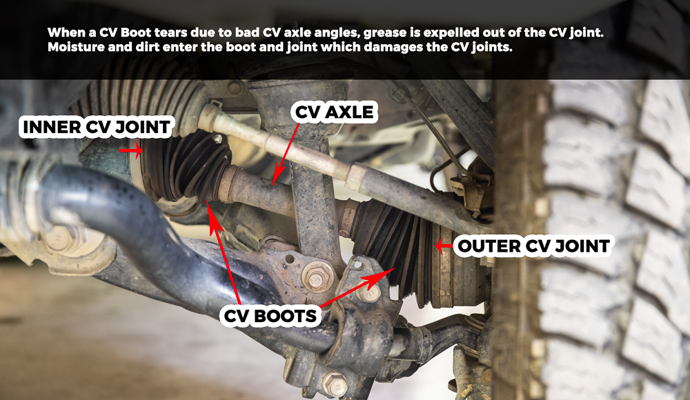
- CV Axle (Constant Velocity Axle): Transfers power from the front differential to the front wheels. 4Runners are typically four-wheel drive (4WD) or all-wheel drive (AWD), requiring these axles.
- Bump Stops: Limit upward suspension travel to prevent damage to other components.
Key Specifications
Specifications will vary greatly depending on the year and trim of your 4Runner. Common specs to be aware of are:
- Torque Specifications: Essential for tightening fasteners correctly. Consult your repair manual for specific torque values. Over-tightening can damage components, while under-tightening can lead to failures.
- Ride Height: Measuring ride height can help diagnose sagging springs or other suspension issues.
- Alignment Angles: Caster, camber, and toe are critical for proper tire wear and handling. These angles should be checked and adjusted after any suspension work.
Decoding the Diagram: Symbols and Lines
A suspension diagram isn't just a pretty picture; it's a technical drawing with specific conventions. Here's what some common symbols mean:
- Solid Lines: Typically represent physical components like control arms, shocks, and springs. Thicker lines might indicate larger or more structural parts.
- Dashed Lines: Often represent hidden components or lines of action, such as the path of force through a component.
- Arrows: Indicate direction of movement or force. For example, an arrow might show the direction of compression or rebound in a shock absorber.
- Hatching: Often used to indicate a cross-sectional view, showing the internal structure of a component.
- Fasteners: Represented by circles or other symbols to indicate bolts, nuts, and screws. Torque values are often associated with these symbols in more detailed diagrams.
Colors in diagrams are less standardized, but some common uses include:
- Red: Often used to highlight high-stress areas or components requiring special attention.
- Blue: Can represent fluid lines, such as brake lines or power steering lines.
- Green: Might indicate components related to the electrical system.
How It Works: The Suspension in Action
When your 4Runner hits a bump, the tire moves upwards. This movement compresses the coil spring (or twists the torsion bar), which absorbs the energy of the impact. The shock absorber then controls the rate of compression and rebound, preventing the vehicle from bouncing excessively. The control arms allow the wheel to move vertically while maintaining its position relative to the vehicle. The sway bar resists body roll during cornering by transferring force between the left and right sides of the suspension. The steering knuckle pivots on the ball joints, allowing you to steer the vehicle.
It's a complex interaction of forces and movements, all designed to keep your tires in contact with the road and provide a comfortable and controlled ride. The alignment angles (caster, camber, and toe) are critical to ensuring that the tires wear evenly and the vehicle handles properly.
Real-World Use: Basic Troubleshooting
Here are some common suspension problems and how a diagram can help you diagnose them:
- Clunking Noise: Could be a worn ball joint, tie rod end, sway bar link, or shock absorber. The diagram helps you locate these components and visually inspect them for play or damage.
- Excessive Bouncing: Indicates worn shock absorbers. The diagram shows you where to find the shocks and how they are mounted.
- Uneven Tire Wear: Often caused by misaligned suspension. The diagram shows you the components that affect alignment angles, such as the control arms and tie rods.
- Sagging Suspension: Could be caused by worn springs or torsion bars. The diagram helps you identify these components and assess their condition.
Basic Troubleshooting Steps:
- Visual Inspection: Using the diagram, carefully inspect all suspension components for damage, wear, and loose connections.
- Bounce Test: Push down on each corner of the vehicle and observe how it rebounds. Excessive bouncing indicates worn shocks.
- Listen Carefully: Pay attention to any unusual noises while driving, such as clunking, squeaking, or grinding.
Safety First: High-Risk Components
Working on suspension components can be dangerous. Here are some crucial safety precautions:
- Spring Compression: Coil springs store a tremendous amount of energy. Never attempt to disassemble a coil spring without using a proper spring compressor. Improper use of a spring compressor can result in serious injury or death.
- Vehicle Support: Always use jack stands to support the vehicle before working underneath it. Never rely solely on a jack.
- Torque Specifications: Use a torque wrench to tighten fasteners to the correct torque specifications. Over-tightening can damage components, while under-tightening can lead to failures.
- Wheel Alignment: After performing any suspension work, it's essential to have the wheel alignment checked and adjusted by a qualified technician.
- Brake Lines: Be extremely careful when working near brake lines. Damage to a brake line can result in complete brake failure.
Important Note: If you are not comfortable working on suspension components, it's best to take your vehicle to a qualified mechanic. Suspension work can be complex and requires specialized tools and knowledge.
We’ve covered a lot of ground, but remember this is a starting point. As you delve deeper into your 4Runner's front suspension, you'll gain a greater appreciation for the engineering that goes into providing a comfortable and capable ride. And with the downloadable diagram, you’ll have a valuable tool at your fingertips. Get ready to tackle those suspension projects with confidence!
Ready to get your hands on the detailed front suspension diagram? We have the file ready for you! [Provide download link or instructions for accessing the file here. Example: Click here to download the Toyota 4Runner Front Suspension Diagram.]