
Toyota 5 Wire Maf Sensor Wiring Diagram
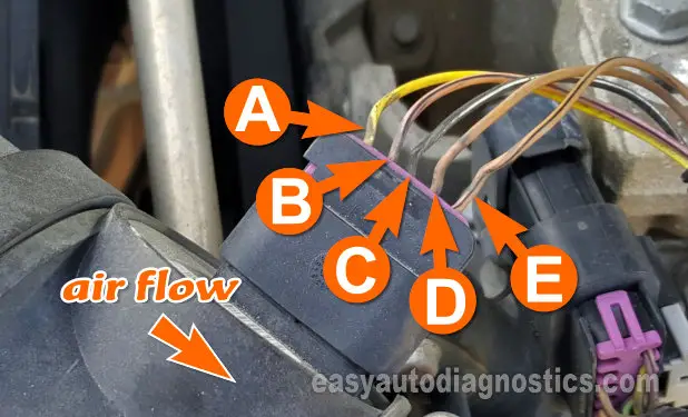
Alright, let's dive into the world of Toyota's 5-wire Mass Air Flow (MAF) sensor wiring diagrams. Understanding this system is crucial for diagnosing engine performance issues, performing modifications, or simply expanding your automotive knowledge. This article will break down the diagram piece by piece, offering insights that even seasoned DIY mechanics will appreciate.
Why This Diagram Matters
Knowing your way around a Toyota 5-wire MAF sensor wiring diagram is invaluable for several reasons:
- Troubleshooting: When your engine's acting up – poor fuel economy, rough idling, or a check engine light staring you down – the MAF sensor is often a prime suspect. The wiring diagram lets you pinpoint connection issues, shorts, or open circuits within the sensor's wiring harness.
- Modifications: If you're upgrading your intake system or installing a standalone engine management system (EMS), understanding the MAF sensor wiring is essential for proper integration and avoiding performance hiccups.
- Repairs: Damaged wiring or connectors? The diagram helps you identify the correct wires for splicing or replacing sections of the harness.
- Learning: Even if you're not actively working on your car, understanding how the MAF sensor functions and how it's wired provides valuable insights into your engine's operation.
Key Specs and Main Parts of the 5-Wire MAF Sensor
The 5-wire configuration provides a more sophisticated method for air mass measurement, enhancing accuracy and responsiveness compared to older MAF sensor designs. Here are the core components and their functions:
- MAF Sensor Housing: This is the physical body of the sensor, usually mounted in the intake tract, allowing air to flow through it.
- Hot-Wire or Hot-Film Element: This is the heart of the sensor. A heated element (either a wire or a film) is maintained at a constant temperature. As air flows past it, the element cools. The amount of current required to maintain the element's temperature is directly proportional to the mass of air flowing through the sensor.
- Temperature Sensor (IAT - Intake Air Temperature Sensor): Integrated within the MAF sensor, the IAT sensor measures the temperature of the incoming air. This information is used to compensate for air density changes due to temperature, ensuring accurate mass airflow readings. This is often one of the five wires.
- Signal Wire (MAF Output): This wire transmits the voltage signal representing the mass airflow reading to the engine control unit (ECU).
- Ground Wires: One or more ground wires provide a return path for the electrical circuits within the MAF sensor. Some Toyotas use a dedicated sensor ground to minimize noise.
- Power Supply Wire: This wire supplies the necessary voltage (typically 12V or 5V, check your specific model) to power the heating element and other electronic components within the sensor.
Decoding the Diagram: Symbols, Lines, and Colors
A wiring diagram is a visual representation of the electrical circuits. Understanding the symbols is key to interpreting the information it contains.
- Lines: Lines represent wires. Thicker lines often indicate higher current carrying capacity. Dashed lines can represent shielded wiring.
- Colors: Wire colors are critical for identification. Standard colors include (but aren't limited to):
- Red (R): Typically indicates a power supply wire.
- Black (B): Usually a ground wire.
- White (W): Often a signal wire.
- Blue (L): Can be used for various signals.
- Green (G): Can be used for various signals, often sensor related.
- Yellow (Y): Can be used for various signals.
- Symbols:
- Circles: Often represent connection points or terminals.
- Resistors: Zigzag lines representing components that resist electrical current.
- Ground Symbol (often three horizontal lines decreasing in size): Indicates a connection to the vehicle's chassis ground.
- ECU/PCM: A rectangle representing the Engine Control Unit (ECU) or Powertrain Control Module (PCM). The wires connected to the ECU will be labeled with their pin numbers.
- MAF: An abbreviation of Mass Air Flow, identifying the MAF sensor in the diagram.
How It Works: From Airflow to ECU Signal
The 5-wire MAF sensor works on the principle of hot-wire anemometry. Here's a breakdown of the process:
- Power Up: The ECU supplies power to the MAF sensor, energizing the hot-wire or hot-film element.
- Heating: The heating element is heated to a specific temperature, maintained by a control circuit within the sensor.
- Airflow Cooling: As air flows through the sensor housing and across the heated element, it cools the element.
- Current Compensation: The control circuit increases the current flowing through the element to maintain its constant temperature. The amount of current required is directly proportional to the mass of air flowing past the element.
- Signal Generation: The sensor's internal circuitry converts the current reading into a voltage signal. This voltage signal is the MAF output signal, sent to the ECU.
- ECU Interpretation: The ECU reads the MAF sensor signal and uses it, along with other sensor inputs (like the IAT sensor reading from the integrated IAT sensor on the MAF), to calculate the amount of fuel to inject into the engine, adjust ignition timing, and control other engine parameters.
Real-World Use: Basic Troubleshooting Tips
Here are some common troubleshooting scenarios and how the wiring diagram can help:
- No MAF Signal: Use a multimeter to check for voltage at the MAF sensor's power supply wire. If there's no voltage, trace the wire back to the power source (often a fuse or relay) using the wiring diagram. Also, check the ground wires for continuity to the vehicle's chassis.
- High or Low MAF Readings: These could indicate a faulty sensor, but also check for wiring issues. Look for shorts to ground or voltage, or open circuits in the signal wire. A broken wire might still make *some* contact, leading to erratic readings.
- IAT Sensor Issues: If the IAT sensor is integrated with the MAF, you can use the wiring diagram to check the IAT sensor's signal wire and ground. A faulty IAT sensor can skew the MAF readings and affect engine performance.
- Check Engine Light (CEL): Use an OBD-II scanner to retrieve the diagnostic trouble code (DTC). Many DTCs will point directly to the MAF sensor (e.g., P0100, P0101, P0102, P0103). The wiring diagram helps you verify the sensor's wiring and connections before replacing the sensor.
Safety First! Handling Risky Components
Working with automotive electrical systems involves inherent risks. Keep these points in mind:
- Disconnect the Battery: Always disconnect the negative battery terminal before working on any electrical components. This prevents accidental shorts and potential electrical shocks.
- Airbag Systems: Be extremely cautious when working near airbag system wiring. Accidental activation of an airbag can cause serious injury. Consult your vehicle's repair manual for specific safety precautions.
- Fuel System: The MAF sensor is part of the engine management system, which controls fuel delivery. Avoid creating sparks or open flames near the fuel system.
- Proper Tools: Use properly insulated tools designed for automotive electrical work. This minimizes the risk of electrical shock.
- Consult a Professional: If you're uncomfortable working on your vehicle's electrical system, consult a qualified mechanic.
With this knowledge, you should be much more comfortable tackling MAF sensor related issues. Remember, always refer to the specific wiring diagram for your vehicle model and year. And if you are seeking the wiring diagram, we have the file available and ready for download. Happy wrenching!