
Toyota 5 Wire Mass Air Flow Sensor Wiring Diagram
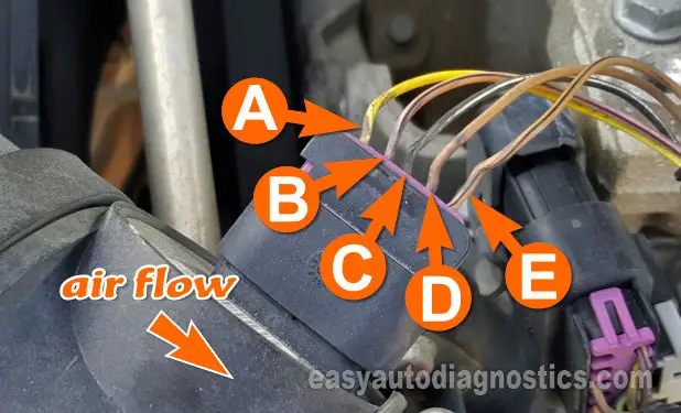
Hey there, gearheads! Ever wondered what's lurking inside that seemingly simple Mass Air Flow (MAF) sensor on your Toyota? Especially the 5-wire versions? Well, you're in the right place. We're diving deep into the wiring diagram of these sensors, explaining what each wire does, how the system works, and some basic troubleshooting to keep your Toyota running smoothly. Whether you're tackling a repair, planning a modification, or just expanding your automotive knowledge, understanding the MAF sensor is crucial.
Why This Diagram Matters
The MAF sensor is a critical component of your engine's fuel management system. A faulty MAF sensor can lead to a whole host of problems, including poor fuel economy, rough idling, stalling, and even a check engine light (CEL). Having the wiring diagram handy is invaluable for:
- Diagnosis: Accurately pinpointing wiring issues or sensor failures.
- Repair: Correctly splicing wires, replacing connectors, or rewiring the sensor.
- Modification: Safely tapping into sensor signals for aftermarket performance enhancements (like piggyback ECUs).
- Learning: Gaining a deeper understanding of your engine's control systems.
Simply put, this diagram is your roadmap to understanding and working on your Toyota's MAF sensor.
Key Specs and Main Parts
Before we jump into the diagram, let's define the major players and their roles. A 5-wire MAF sensor typically contains the following:
- Hot-wire Anemometer: This is the core technology. A thin wire is heated to a constant temperature. As air flows past it, it cools down. The amount of current required to maintain the temperature is directly proportional to the mass airflow.
- Temperature Sensor (IAT): Integrated Air Temperature sensor. This measures the incoming air temperature. This information is crucial because the density of air changes with temperature, affecting the mass calculation.
- Sensor Housing: The physical structure that mounts in the intake tract and houses the sensor components.
- Connector: The electrical connector that provides the interface between the sensor and the engine control unit (ECU).
Now, let's look at the typical functions of each of the 5 wires. Keep in mind that wire colors can vary by model year and specific Toyota vehicle, so always verify with your specific vehicle's wiring diagram.
- +12V Power Supply (B+): Provides the necessary voltage for the hot-wire anemometer circuit to operate. This is often connected to the ignition switch.
- Ground (GND): Provides the ground reference for the sensor circuits. Ensuring a solid ground connection is essential for accurate readings.
- MAF Signal (VAF): This is the analog voltage signal outputted by the MAF sensor. The voltage level varies proportionally with the mass airflow. The ECU uses this signal to calculate the amount of fuel to inject.
- Intake Air Temperature (IAT) Signal: This is the analog voltage signal outputted by the IAT sensor, representing the intake air temperature.
- MAF Heater Control: This wire controls the heater element that maintains the hot-wire at a constant temperature. The ECU regulates this voltage.
Understanding the Wiring Diagram Symbols
Wiring diagrams use a standard set of symbols to represent components and connections. Let's break down the most common ones you'll encounter in a Toyota MAF sensor diagram:
- Solid Lines: Represent wires connecting different components. The thickness of the line usually doesn't carry any specific meaning.
- Dotted Lines: May indicate shielding or a less critical connection.
- Connectors: Depicted as squares or rectangles with pins inside. Arrows or labels often indicate the direction of the connection.
- Ground Symbols: Represent electrical grounding points. There are typically chassis grounds or sensor grounds.
- Resistors: Shown as zigzag lines. You may not see discrete resistors in the diagram itself, but the hot-wire anemometer *is* a resistor.
- Capacitors: Represented by two parallel lines.
- Voltage Source (B+): Depicted as a circle with a "+" sign inside, indicating a positive voltage supply.
Color Codes: Wire colors are typically abbreviated using standard codes, such as: B (Black), R (Red), W (White), G (Green), L (Blue), Y (Yellow), Br (Brown), and P (Pink). For example, "R/W" would indicate a red wire with a white stripe.
How It Works: A Closer Look
The 5-wire MAF sensor works on the principle of hot-wire anemometry. Here's a simplified explanation:
- The ECU sends a controlled voltage to the heater circuit.
- The hot-wire is heated to a specific temperature.
- As air flows through the sensor housing and across the hot-wire, it cools the wire down.
- The sensor's internal circuitry increases the current flowing through the hot-wire to maintain its original temperature.
- The amount of current needed to maintain the temperature is directly proportional to the mass of air flowing through the sensor.
- The sensor outputs a voltage signal (MAF Signal) that represents the mass airflow. The ECU reads this signal and uses it to calculate the appropriate amount of fuel to inject.
- Simultaneously, the IAT sensor measures the temperature of the incoming air and sends a separate voltage signal to the ECU. This information is used to correct for air density changes.
The ECU then uses both the MAF signal and the IAT signal, along with other sensor inputs (like engine speed and throttle position), to calculate the optimal air-fuel ratio for efficient combustion.
Real-World Use: Basic Troubleshooting Tips
Here are some basic troubleshooting steps you can perform if you suspect a problem with your MAF sensor:
- Visual Inspection: Check the sensor and connector for any signs of damage, corrosion, or loose wires.
- Scan for Codes: Use an OBD-II scanner to check for any stored diagnostic trouble codes (DTCs) related to the MAF sensor (e.g., P0100, P0101, P0102).
- Check Power and Ground: Use a multimeter to verify that the sensor is receiving the correct voltage and has a good ground connection.
- Signal Output Test: With the engine running, use a multimeter or oscilloscope to monitor the MAF signal voltage. The voltage should change smoothly as the engine speed increases.
- IAT Sensor Check: Verify the IAT sensor reading is within a reasonable range and changes as the intake air temperature changes.
Cleaning: A dirty MAF sensor can sometimes cause problems. Use a specialized MAF sensor cleaner to gently clean the hot-wire element. Do not use anything else, as you could damage the delicate sensor.
Remember: A faulty MAF sensor can mimic the symptoms of other engine problems, so it's crucial to perform a thorough diagnosis before replacing the sensor.
Safety First
Working on electrical systems can be dangerous. Here are some important safety precautions:
- Disconnect the Battery: Always disconnect the negative battery terminal before working on any electrical components.
- Be Careful with Wiring: Avoid short-circuiting wires. Use insulated tools and be mindful of where you're placing your hands.
- Avoid Water: Never work on electrical systems in wet conditions.
- The Hot Wire is very sensitive and easily damaged, do not touch it!
Airbag Systems: Be aware that some wiring harnesses may be located near airbag components. Exercise extreme caution when working in these areas to avoid accidental airbag deployment. Consult your vehicle's repair manual for specific safety procedures related to airbag systems.
Get Your Diagram!
Now that you've got a handle on the basics, you're ready to tackle your Toyota's 5-wire MAF sensor with confidence. Remember to consult your specific vehicle's wiring diagram for accurate information. We have a generic wiring diagram file available for download, which provides a general representation of the wiring layout. Keep in mind that wire colors and pin assignments can vary, so always double-check with your vehicle's specific documentation. Click the download button below to access the file!
We hope this comprehensive guide has been helpful. Good luck with your repairs and modifications!