
Toyota Camry Front Suspension Diagram
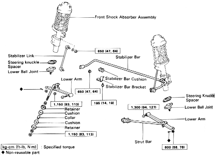
The Toyota Camry, a mainstay of reliability and practicality, owes much of its smooth ride and predictable handling to its well-engineered front suspension system. Understanding the intricacies of this system is crucial for anyone looking to perform maintenance, troubleshoot issues, or even consider performance upgrades. This article will delve into a detailed Toyota Camry front suspension diagram, breaking down its components, functionality, and practical applications.
Purpose of Understanding the Diagram
Why bother with a diagram? Simply put, knowledge is power. A detailed diagram of the front suspension empowers you to:
- Perform accurate diagnostics: Pinpoint the source of noises, vibrations, or handling problems.
- Execute precise repairs: Ensure proper component placement and torque specifications during replacements.
- Plan modifications: Evaluate the impact of aftermarket parts like lowering springs or upgraded shocks.
- Increase your understanding: Develop a deeper appreciation for automotive engineering.
For the DIY mechanic, this means saving money on labor costs and gaining confidence in tackling suspension-related issues. For modders, it's about making informed decisions to achieve the desired performance characteristics. For anyone simply curious about how their car works, it provides valuable insight into a critical system.
Key Specs and Main Parts of a Camry Front Suspension
The Camry typically uses a MacPherson strut front suspension. This design is favored for its relatively compact size, simplicity, and cost-effectiveness. Here's a breakdown of the main components:
- Strut Assembly: The heart of the system. It combines the shock absorber (dampens oscillations) and the coil spring (supports the vehicle's weight) into a single unit.
- Coil Spring: A helical spring that absorbs vertical impacts and maintains ride height. Spring rates are critical for ride comfort and handling.
- Shock Absorber (Damper): Controls the rate at which the spring compresses and rebounds, preventing excessive bouncing. Common types include hydraulic and gas-charged dampers.
- Lower Control Arm (LCA): A pivoting arm that connects the wheel hub to the vehicle's frame. It controls the wheel's movement in the vertical plane.
- Ball Joint: A spherical bearing that allows the wheel hub to pivot for steering. It connects the lower control arm to the steering knuckle.
- Steering Knuckle (Upright): The structural component that holds the wheel hub, bearings, and brake components.
- Tie Rod End: Connects the steering rack to the steering knuckle, transmitting steering input to the wheels.
- Sway Bar (Anti-Roll Bar): A torsion bar that connects the left and right sides of the suspension. It resists body roll during cornering.
- Sway Bar Link: Connects the sway bar to the strut assembly or lower control arm.
- Wheel Hub and Bearings: Allows the wheel to rotate freely and provides a mounting point for the wheel.
- Bushings: Rubber or polyurethane components that dampen vibrations and allow for controlled movement between suspension parts.
Important Specs to Consider:
- Spring Rate: Measured in lbs/inch (or N/mm), indicating how much force is required to compress the spring a certain distance.
- Shock Absorber Damping Force: Determines how quickly the shock absorber dissipates energy.
- Ride Height: The distance between the ground and a specific point on the vehicle's frame.
- Alignment Angles: Caster, camber, and toe angles, which affect handling and tire wear.
Understanding Diagram Symbols
A detailed diagram utilizes symbols to represent different components and their connections. Here's a general guide:
- Solid Lines: Typically represent physical connections between parts (e.g., bolts, welds).
- Dashed Lines: Might indicate hidden lines, internal components, or fluid lines (e.g., brake lines).
- Arrows: Indicate direction of movement or force. For example, an arrow on a tie rod might show the direction of steering force.
- Color Coding: Some diagrams use colors to differentiate between materials (e.g., steel, aluminum, rubber) or systems (e.g., brake system, steering system). However, most diagrams available to DIYers are black and white.
- Torque Specifications: Numbers often appear next to bolts or fasteners, indicating the required torque in Nm or lb-ft. This is critical for safe and proper assembly.
Legend or key of symbols and abbreviation is commonly found on a corner of the diagram.
How the Camry Front Suspension Works
The MacPherson strut suspension is designed to allow vertical wheel movement while maintaining proper steering geometry. When the wheel encounters a bump:
- The wheel moves upwards, compressing the coil spring.
- The shock absorber dampens the spring's oscillation, preventing excessive bouncing.
- The lower control arm pivots, allowing the wheel to move vertically while maintaining its lateral position.
- The ball joint allows the steering knuckle to pivot for steering.
- The sway bar resists body roll during cornering by transferring force from one side of the suspension to the other.
The entire system works in concert to provide a comfortable ride, predictable handling, and stable steering.
Real-World Use: Basic Troubleshooting
Armed with a diagram and a basic understanding, you can start troubleshooting common suspension problems:
- Clunking Noise: Could indicate worn ball joints, tie rod ends, sway bar links, or strut mounts. Visually inspect these components for play or damage.
- Bouncing Ride: Likely caused by worn shock absorbers. A simple "bounce test" (pushing down on each corner of the car and observing how quickly it settles) can provide clues.
- Uneven Tire Wear: Often a sign of misalignment. Check the alignment angles and adjust as needed.
- Vibration: Could be caused by unbalanced tires, bent wheels, or worn wheel bearings.
- Steering Wander: May indicate worn tie rod ends, ball joints, or control arm bushings.
Remember to always consult your vehicle's service manual for specific diagnostic procedures and torque specifications.
Safety Considerations
Working on suspension components can be dangerous if proper precautions aren't taken.
- Spring Compression: Coil springs store a tremendous amount of energy. Never attempt to disassemble a strut assembly without a proper spring compressor. Releasing a compressed spring can cause serious injury or death.
- Vehicle Support: Always use jack stands to support the vehicle securely before working underneath it. Never rely solely on a jack.
- Torque Specifications: Always tighten fasteners to the specified torque. Under-tightening can lead to component failure, while over-tightening can damage threads.
- Brake Lines: Be extremely careful when working near brake lines. Damaging a brake line can result in brake failure.
- Professional Help: If you're not comfortable working on suspension components, seek the help of a qualified mechanic. Certain repairs, like strut replacement or alignment, often require specialized tools and expertise.
A note on struts: Struts contain a compressed gas that can cause injury if the strut is punctured without being properly disassembled with a spring compressor.
Diagram Availability
This article provides a general overview of the Toyota Camry front suspension. For detailed diagrams specific to your Camry's year and model, we have the file, and the reader can download the diagram. Remember to always cross-reference the diagram with your vehicle's service manual for accurate information.