
Toyota Camry Rear Suspension Diagram
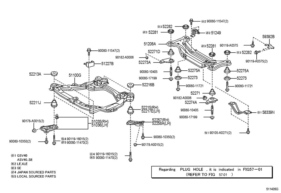
So, you're looking to dive into the rear suspension of your Toyota Camry, eh? Smart move! Understanding this system is crucial for everything from routine maintenance and troubleshooting annoying clunks to making informed decisions about performance upgrades. This isn't just about fixing a squeak; it's about understanding how your car interacts with the road. This article will break down a typical Camry rear suspension diagram, explain what all those squiggles and lines mean, and give you the know-how to diagnose common issues. Remember, always consult your specific Camry model's repair manual for the most accurate information.
Why Bother with a Suspension Diagram?
Why are we even talking about this? Suspension diagrams are invaluable tools for several reasons:
- Troubleshooting: Identifying the specific component causing a problem, whether it's a worn bushing or a leaky shock absorber.
- Repairs: Knowing the correct order of assembly and disassembly, torque specifications, and the location of all necessary hardware.
- Modifications: Planning and executing suspension upgrades, such as installing lowering springs, performance shocks, or sway bars. A diagram will help you understand the geometry and impact of any changes.
- Learning: Simply understanding how your car works! It's empowering to know what's happening beneath the surface.
Key Specs and Main Parts of a Typical Camry Rear Suspension
While specific designs vary slightly depending on the Camry model year (check your manual!), most Camrys utilize a dual-link or multi-link independent rear suspension system. This design allows each rear wheel to move independently, improving ride quality and handling compared to a simpler solid axle design. Here's a breakdown of the key components you'll find in a typical rear suspension diagram:
- Shock Absorber (Damper): Controls spring oscillation and absorbs bumps. Critical for ride comfort and handling.
- Coil Spring: Supports the weight of the vehicle and provides ride height.
- Lower Control Arm (Lateral Link): Connects the wheel hub to the vehicle's frame. Controls wheel movement in the vertical and lateral directions. Usually the main load-bearing arm.
- Upper Control Arm (Trailing Link or Camber Link): Another link connecting the hub to the frame, further refining wheel movement and contributing to stability. Often adjustable for camber.
- Trailing Arm (on some models): Extends from the hub forward to a pivot point on the frame. Helps control fore-and-aft wheel movement.
- Sway Bar (Anti-Roll Bar): Connects the left and right sides of the suspension, reducing body roll during cornering.
- Wheel Hub/Bearing Assembly: Houses the wheel bearing and provides a mounting point for the wheel.
- Knuckle (Upright): Connects all the suspension links to the wheel hub.
- Bushings: Rubber or polyurethane components that isolate vibrations and allow for controlled movement between suspension parts. These are often a common failure point.
Don't get overwhelmed by all the parts! The diagram will clearly show how they connect and interact. Important Specs to Note: Wheel alignment angles (camber, toe, caster), torque specifications for fasteners, and shock absorber damping rates (if adjustable).
Understanding the Diagram: Symbols and Lines
A suspension diagram isn't just a pretty picture; it's a technical drawing with standardized symbols. Here's a quick guide:
- Solid Lines: Represent physical components, such as control arms, shocks, and springs.
- Dashed Lines: Often indicate hidden lines or components located behind other parts.
- Centerlines: Usually shown as a long dash followed by a short dash, these indicate the center of a component or a line of symmetry.
- Arrows: Used to indicate the direction of movement, such as suspension travel or the application of torque.
- Hatching: Used to indicate a sectioned area, often showing the internal construction of a component.
- Torque Specifications: Often listed next to the fastener in Newton-meters (Nm) or foot-pounds (ft-lbs). Always use a torque wrench!
Color Coding: While not always present, some diagrams use color coding to differentiate between different types of lines or components. Consult the diagram's legend for specific color meanings. For instance, hydraulic lines might be colored blue.
How It Works: A Simplified Explanation
The rear suspension's job is to keep the tires in contact with the road, providing grip for acceleration, braking, and cornering, while also absorbing bumps and vibrations to provide a comfortable ride.
When the wheel encounters a bump, the suspension compresses. The coil spring absorbs the initial impact. The shock absorber (or damper) then dampens the spring's oscillations, preventing the car from bouncing excessively. The control arms guide the wheel's movement, keeping it aligned properly. The sway bar resists body roll during cornering by transferring force from one side of the suspension to the other. This intricate dance of components allows the wheels to move independently, maximizing grip and stability.
Think of it like this: the spring provides the cushion, and the shock absorber controls the bounce. The control arms ensure the wheel moves in a predictable and controlled manner.
Real-World Use: Basic Troubleshooting
Here are a few common suspension problems and how a diagram can help you diagnose them:
- Clunking Noises: Often caused by worn bushings or loose fasteners in the control arms. The diagram helps you locate all the bushings and check their condition.
- Squeaking Noises: Can be caused by dry or worn bushings, or by metal-to-metal contact due to a broken component. The diagram can point you to potential friction points.
- Excessive Bouncing: Indicates worn shock absorbers. The diagram confirms their location and allows you to visually inspect them for leaks.
- Uneven Tire Wear: Can be caused by misaligned suspension components, such as bent control arms or worn ball joints (although less common in rear suspension). The diagram helps you identify the relevant components for inspection.
- "Wallowing" Feeling: Usually caused by a worn sway bar or its connecting links.
Using the Diagram: When troubleshooting, start by identifying the location of the noise or symptom. Then, use the diagram to pinpoint the relevant components in that area. Visually inspect the components for wear, damage, or looseness. Always compare both sides of the vehicle to identify discrepancies.
Safety First! Risky Components
Working on suspension components can be dangerous due to the stored energy in the springs. Here are a few safety precautions to keep in mind:
- Spring Compression: Compressing coil springs requires specialized tools (spring compressors). Improper use can result in serious injury! If you're not comfortable using these tools, take your vehicle to a professional.
- Support the Vehicle: Always use jack stands to support the vehicle before working on the suspension. Never rely solely on a jack.
- Loosen Fasteners Carefully: Some suspension fasteners may be heavily corroded and require significant force to loosen. Use penetrating oil and appropriate tools to avoid damaging the fasteners or injuring yourself.
- Wheel Alignment: After replacing certain suspension components (especially control arms), a wheel alignment is essential to ensure proper handling and tire wear.
- Brake Lines: Be extremely careful when working near brake lines. Damaging a brake line can result in a loss of braking power.
Important Note: Always consult your vehicle's repair manual for specific safety precautions and procedures. When in doubt, seek professional assistance.
Understanding your Toyota Camry's rear suspension can seem daunting, but armed with a diagram and some basic knowledge, you can confidently tackle maintenance, repairs, and even performance upgrades. It's about knowing what's under there and how it all works together.
And, to help you on your way, we have the full high-resolution diagram file ready for you to download. Happy wrenching!