Toyota Corolla 2006 Fuse Box Diagram
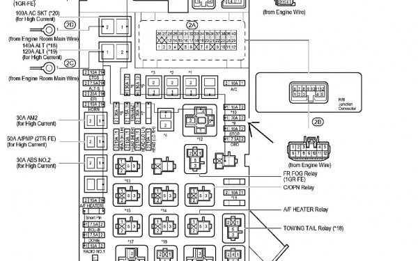
Let's dive into the Toyota Corolla 2006 fuse box diagram. This isn't just some piece of paper; it's your roadmap to understanding and troubleshooting your Corolla's electrical system. Whether you're dealing with a blown fuse, planning a modification, or just want to understand your car better, a good grasp of this diagram is essential.
Purpose of the Fuse Box Diagram
The fuse box diagram serves several crucial purposes:
- Diagnosis and Repair: When an electrical component stops working – a headlight, the radio, or even the engine starting – the first place to check is the fuses. The diagram tells you which fuse corresponds to which circuit.
- Modifications: Planning to install aftermarket accessories like a sound system or auxiliary lighting? The diagram helps you identify suitable points to tap into the electrical system, ensuring you don't overload circuits.
- Understanding Your Vehicle: Beyond repairs, the diagram allows you to learn how your Corolla's electrical system is laid out. This knowledge is invaluable for any DIY enthusiast.
Key Specs and Main Parts of the 2006 Corolla Fuse System
The 2006 Corolla typically has two main fuse box locations:
- Interior Fuse Box: Usually located under the dashboard on the driver's side. This box houses fuses for interior components like the radio, lights, power windows, and accessories.
- Engine Compartment Fuse Box: Situated in the engine bay, this box protects critical engine management and vehicle systems. It includes fuses for the engine control unit (ECU), fuel pump, ignition system, and cooling fan.
Understanding the voltage and amperage ratings is key. The Corolla 2006, like most cars, operates on a 12-volt DC (Direct Current) system. Fuses are rated in amperes (amps, A), which indicates the maximum current the fuse can handle before it blows. Using a fuse with a higher amperage than specified is dangerous, as it can allow excessive current to flow, potentially damaging components and causing a fire. Always use the correct amperage rating as indicated on the fuse box diagram or the fuse itself.
Understanding the Symbols, Lines, Colors, and Icons
A fuse box diagram isn't just a list of numbers; it's a visual language. Here's a breakdown of common elements:
- Fuses: Usually represented by a rectangle with a wavy line through it. The amperage rating is typically printed next to the symbol (e.g., 15A, 20A).
- Relays: Often shown as a square with a coil symbol inside. Relays are electrically operated switches that control higher-current circuits, like the headlights or starter motor.
- Lines: Indicate the wiring connections between fuses, relays, and components. Different line thicknesses might represent different wire gauges (thicker lines indicate heavier gauge wires).
- Colors: While the diagram itself might not be in color (most are black and white), knowing the wire colors in your car is crucial. Toyota typically uses a standardized color coding system (e.g., red for power, black for ground). You can find the specific wire color codes for the 2006 Corolla in the official service manual, which is beyond the scope of this article.
- Icons: Icons represent the components that the fuses protect. For example, a light bulb icon indicates a fuse for the headlights or taillights, and a radio icon signifies the fuse for the audio system.
Important Note: Diagrams might use abbreviations (e.g., "IGN" for ignition, "ECU" for engine control unit). Refer to the legend in the diagram or the service manual for a complete listing of abbreviations.
How It Works: The Circuit Protection System
The fuse box is the heart of the car's electrical protection system. Each fuse is a weak link designed to break the circuit if the current exceeds a safe level. When a short circuit or overload occurs, the fuse's internal filament melts, interrupting the flow of electricity and preventing damage to the protected component. This is why diagnosing a blown fuse is the first step in many electrical repairs.
Relays, on the other hand, are used to control high-current circuits with a low-current signal. For example, the headlight switch in your Corolla controls a small current to activate the headlight relay. The relay then closes a circuit, allowing a much larger current to flow to the headlights. This protects the headlight switch from damage due to the high current demand of the headlights.
Real-World Use: Basic Troubleshooting Tips
Here's how to use the fuse box diagram for troubleshooting:
- Identify the Problem: Determine which component is not working (e.g., the windshield wipers).
- Consult the Diagram: Locate the fuse or relay associated with that component on the fuse box diagram.
- Inspect the Fuse: Physically examine the fuse. A blown fuse will have a broken filament visible through the clear plastic housing.
- Replace the Fuse: If the fuse is blown, replace it with a new fuse of the exact same amperage rating. Never use a higher amperage fuse.
- Test the Component: After replacing the fuse, test the component to see if it now works.
- If the Fuse Blows Again: If the new fuse blows immediately or shortly after being replaced, there is a short circuit or overload in the circuit. This requires further investigation by a qualified mechanic. Do not keep replacing fuses without addressing the underlying issue.
A multimeter can be invaluable for diagnosing electrical problems. You can use it to check for voltage at the fuse terminals, test for continuity in a circuit, and measure current draw. If you're not comfortable using a multimeter, consult a professional.
Safety Considerations: Highlighting Risky Components
Working with automotive electrical systems involves inherent risks. Here are some critical safety precautions:
- Disconnect the Battery: Before working on the electrical system, always disconnect the negative (-) terminal of the battery. This prevents accidental short circuits and electrical shocks.
- Avoid Water: Never work on the electrical system in wet conditions.
- High-Current Circuits: Be extremely cautious when working with high-current circuits, such as the starter motor and alternator. These circuits can deliver a significant electrical shock.
- Airbag System: The airbag system is a highly sensitive and potentially dangerous electrical system. Do not attempt to work on the airbag system unless you are properly trained and equipped. Accidental deployment of an airbag can cause serious injury.
- ECU (Engine Control Unit): The ECU is the "brain" of your car and is very sensitive to voltage spikes and static electricity. When working near the ECU, take precautions to avoid static discharge (e.g., use an anti-static wrist strap).
Caution: The information provided here is for general guidance only and should not be considered a substitute for professional advice. Always consult the Toyota Corolla 2006 service manual for detailed information and specific procedures.
Remember, working on your car can be rewarding, but safety is paramount. If you're not confident in your abilities, seek the assistance of a qualified mechanic.
We have a downloadable file containing the Toyota Corolla 2006 fuse box diagram readily available. You can use it as reference for any electrical work and troubleshooting.