
Toyota Ignition Switch Wiring Color Code
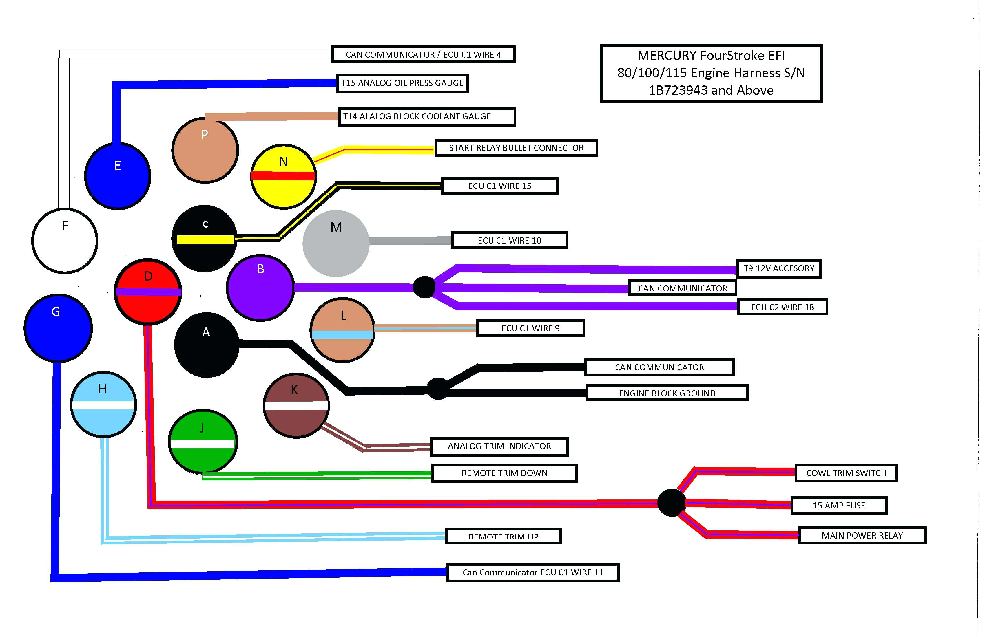
Understanding the Toyota ignition switch wiring color code is crucial for anyone tackling electrical repairs, modifications, or even just wanting a deeper understanding of their vehicle's starting system. It's not just about identifying wires; it's about understanding the flow of electricity that brings your engine to life. This knowledge empowers you to diagnose issues, safely make modifications, and potentially save a significant amount of money on professional repairs.
Purpose: Why You Need This Knowledge
The ignition switch is the command center for your vehicle's starting sequence. Knowing its wiring layout is essential for:
- Troubleshooting Starting Problems: Pinpointing faulty wiring or a failing ignition switch.
- Security System Installation: Integrating aftermarket alarms and remote start systems requires precise wiring connections.
- Keyless Entry Systems: Similar to security systems, adding keyless entry demands accurate wiring knowledge.
- Modifications: Custom wiring projects, such as adding auxiliary power sources or modifying lighting circuits, often involve tapping into the ignition system.
- Understanding Your Vehicle: For the curious and mechanically inclined, it provides a valuable insight into how your car works.
Key Specs and Main Parts of the Ignition Switch
The Toyota ignition switch, like most, isn't just a simple on/off switch. It's a multi-position switch that controls various circuits within the car. The typical positions are:
- Lock (0): Steering wheel locked, key can be inserted or removed. No electrical circuits are energized.
- Accessory (ACC): Some accessories like the radio and cigarette lighter are powered on.
- On (IGN): The main ignition circuit is energized. This powers the engine management system (EMS), fuel pump, and other essential components.
- Start (STR): The starter motor is engaged, cranking the engine. This position is spring-loaded and returns to the 'On' position when released.
Key Components:
- Ignition Switch Body: The physical housing that contains the switch mechanism and electrical contacts.
- Wiring Harness Connector: The connector that attaches the wiring harness to the ignition switch. This is where the different colored wires are located.
- Electrical Contacts: Metal contacts inside the switch that make or break electrical circuits based on the key position.
Symbols and Color Codes in a Toyota Ignition Switch Wiring Diagram
Understanding the symbols and color codes used in a wiring diagram is crucial. Think of it as reading a map of your car's electrical system.
Symbols:
- Solid Lines: Represent wires. Thicker lines might indicate wires carrying higher current.
- Dashed Lines: Often represent ground connections or shielded wires.
- Circles: Typically represent connection points or splices.
- Rectangles: Can represent components like relays, fuses, or the ignition switch itself. Look for labels inside the rectangle to identify the component.
- "G" or Ground Symbol: Indicates a connection to the vehicle's chassis, providing a return path for the electrical current. Proper grounding is critical for electrical system function.
Color Codes:
Toyota, like most manufacturers, uses a standardized color code system for wiring. While there can be slight variations depending on the year and model, some common colors and their typical functions are:
- B (Black): Ground. This is almost always a ground wire.
- R (Red): Battery Positive (+12V) or Main Power Supply.
- W (White): Often used for lighting circuits.
- Y (Yellow): Typically used for ignition circuits.
- G (Green): Can be used for various signals, including indicator lights or sensor inputs.
- L (Blue): Often used for lighting or accessory circuits.
- Br (Brown): Can be used for accessories or sensor signals.
Important Notes on Color Codes:
- Color Combinations: Wires can have a primary color and a stripe (e.g., W-B = White with a Black stripe). The first letter indicates the base color, and the second indicates the stripe color.
- Model Specific Variations: Always consult the wiring diagram specific to your year and model Toyota. Color codes can shift between generations and even within the same model line. Relying solely on general color codes can lead to misdiagnosis and potentially damage your vehicle's electrical system.
How the Ignition Switch Works
The ignition switch is essentially a series of switches housed in one unit. Each position of the key activates different combinations of these switches, routing power to the appropriate circuits.
- Lock: No circuits are active. The mechanical lock engages, preventing steering and potentially gear shifting.
- Accessory: The switch connects the battery to the accessory circuit. This allows you to use the radio, power windows, and other non-essential functions without the engine running.
- On (Ignition): The switch connects the battery to the ignition circuit, powering the engine control unit (ECU), fuel pump, ignition system, and other critical components required for the engine to run.
- Start: The switch connects the battery to the starter solenoid. The solenoid then engages the starter motor, which cranks the engine. The 'Start' position also typically interrupts power to some accessories to provide maximum power to the starter.
Real-World Use: Basic Troubleshooting Tips
Here are some basic troubleshooting tips when dealing with ignition switch problems, assuming you have a wiring diagram for your specific vehicle.
- No Start: If the engine doesn't crank at all, check for voltage at the starter solenoid wire (typically a small-gauge wire connected to the starter). If there's no voltage when the key is in the 'Start' position, the issue could be the ignition switch or the wiring between the switch and the solenoid.
- No Power to Accessories: If the accessories don't work in the 'Accessory' position, check the fuse for the accessory circuit. If the fuse is good, use a multimeter to check for voltage at the accessory wire on the ignition switch connector when the key is in the 'Accessory' position.
- Engine Cranks But Doesn't Start: If the engine cranks but doesn't start, the problem is likely not the ignition switch itself. Instead, focus on the fuel system, ignition system (spark plugs, ignition coil), or the ECU. Check the wiring going to these components.
- Use a Multimeter: A multimeter is your best friend. Use it to check for voltage and continuity in the wiring. Continuity tests whether a circuit is complete. Voltage tests whether power is flowing through a circuit.
Troubleshooting Example: Imagine your car won't start. First, check your battery voltage. If the battery is good, use your multimeter to check for voltage on the red wire (typically battery positive) going to the ignition switch connector. If you have voltage there, turn the key to the 'Start' position and check for voltage on the yellow wire (typically the starter wire) coming out of the ignition switch connector. If you have voltage on the red wire but not on the yellow wire when the key is in the 'Start' position, the ignition switch itself is likely faulty.
Safety Considerations
Working with automotive electrical systems can be dangerous. Always take the following precautions:
- Disconnect the Battery: Before working on any electrical component, disconnect the negative terminal of the battery. This prevents accidental shorts and electrical shocks.
- Handle Airbags Carefully: The airbag system is highly sensitive. If you need to remove the steering wheel or any components near the airbag, consult your vehicle's repair manual for proper disabling procedures. Mishandling airbags can result in serious injury. Airbags can deploy with significant force, causing harm.
- Use Proper Tools: Use insulated tools to prevent shorts and protect yourself from electrical shock.
- Refer to the Wiring Diagram: Never guess at wiring connections. Always consult the correct wiring diagram for your specific vehicle.
High-Risk Components: The ignition switch is directly connected to the battery and the starter system, both of which carry high currents. Incorrect wiring can lead to short circuits, fires, and damage to your vehicle's electrical system. Be especially careful when working with the red (battery positive) and yellow (starter) wires.
This article provides a general overview of Toyota ignition switch wiring. Due to model and year variations, a specific wiring diagram for your exact vehicle is indispensable. Remember to work safely, use the right tools, and double-check your connections.
We have a collection of Toyota wiring diagrams available. Contact us for the diagram specific to your model and year.