Toyota Tacoma Brake Controller Wiring Harness
So, you're looking to tackle the brake controller wiring on your Toyota Tacoma? Excellent! This is a common and rewarding project, whether you're installing a new brake controller for towing, troubleshooting an existing setup, or simply expanding your understanding of your truck's electrical system. This document will provide a detailed explanation of the Toyota Tacoma brake controller wiring harness, helping you navigate the connections with confidence. We're assuming you're comfortable with basic automotive electrical work, so we'll focus on the specifics of the Tacoma's system.
Purpose of Understanding the Brake Controller Wiring Harness
Why bother diving into the wiring diagram? Several key reasons:
- Installation: Correctly wiring a brake controller is essential for safe towing. Mismatched wires can lead to trailer brake malfunction, creating a dangerous situation.
- Troubleshooting: If your trailer brakes aren't working as expected, understanding the wiring diagram is crucial for diagnosing the problem. You can systematically check connections and test circuits.
- Modification: Perhaps you're relocating the controller, adding a new connector, or integrating it with an aftermarket system. A solid grasp of the wiring is indispensable for these modifications.
- Learning: Understanding your vehicle’s systems is a rewarding skill.
Key Specs and Main Parts
Before we jump into the diagram itself, let's cover some key specifications and identify the main components of the brake controller system:
Key Specs
- Voltage: The system operates on a 12V DC power.
- Wire Gauge: Pay attention to the wire gauge used for each circuit. Heavier gauge wires (e.g., 10 AWG or 12 AWG) are typically used for power and ground, while lighter gauges might be used for signal wires. The specific gauge will vary depending on the factory tow package (if equipped) and the model year. Consult your Tacoma's specific wiring diagram for the exact gauge.
- Fuses: There are specific fuses in the vehicle's fuse box dedicated to the brake controller circuit. Know their location and amperage rating. These protect the system from overloads.
Main Parts
- Brake Controller: This is the heart of the system. It senses when you apply the brakes in your Tacoma and sends a proportional signal to the trailer brakes.
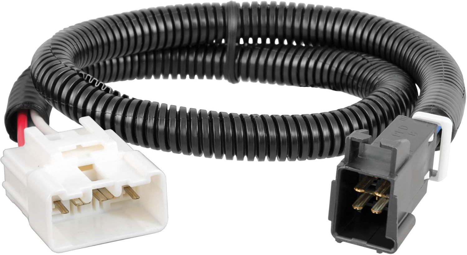
- Brake Controller Wiring Harness: This is the pre-wired harness, often located under the dash on the driver's side, that provides the connection points for the brake controller. It typically has four wires.
- Trailer Connector (7-way or 4-way): This connector at the rear of your Tacoma provides the interface between your truck and the trailer. It carries signals for lights, brakes, and auxiliary power.
- Brake Switch: Located on the brake pedal assembly, this switch signals when you apply the brakes.
- Fuses and Relays: Protect the brake controller and trailer brake circuits.
Symbols and Conventions Explained
Wiring diagrams use standardized symbols to represent components and connections. Understanding these symbols is key to deciphering the diagram.
- Lines: Solid lines represent wires. Dashed lines often represent shielded cables or connections to ground. The thickness of the line can sometimes indicate the wire gauge, but this isn't always consistent.
- Colors: Each wire is color-coded. Common colors include (but are not limited to) Blue (Brake Output), White (Ground), Black (12V Power), and Red (Brake Signal). However, Toyota may use other colors, so rely on your truck's specific diagram, not assumptions.
- Circles/Dots: A filled circle indicates a wire splice or connection point. An open circle may represent a test point.
- Rectangles: Represent components like fuses, relays, and switches. The symbols inside the rectangle will further identify the component.
- Ground Symbol: Usually a series of descending lines, indicating a connection to the vehicle's chassis ground.
- Connectors: Represented by interlocking shapes, connectors show where wires are joined physically. They're often labeled with a code identifying the connector's location and pinout.
How the Brake Controller Wiring Works
The typical brake controller wiring in a Tacoma works as follows:
- Power (12V): A thick gauge wire (typically Black) runs directly from the battery (often through a fuse) to the brake controller. This provides the necessary power for the controller to operate and send current to the trailer brakes.
- Ground: A thick gauge wire (typically White) connects the brake controller to the vehicle's chassis ground. A good ground connection is crucial for proper operation.
- Brake Signal (Input): A wire (often Red or a Red variant) connects the brake controller to the brake light switch. When you press the brake pedal, this wire receives a 12V signal, telling the controller that you are braking.
- Brake Output: A wire (almost always Blue) runs from the brake controller to the trailer connector at the rear of the truck. This wire carries the proportional signal from the brake controller to the trailer brakes. The amount of current sent through this wire determines how strongly the trailer brakes are applied.
The brake controller uses the signal from the brake light switch to determine when to activate the trailer brakes. It then uses an internal algorithm and user-adjustable settings (gain/sensitivity) to determine how much braking force to apply to the trailer. This proportional braking is what makes towing safer and smoother.
Real-World Use: Basic Troubleshooting Tips
Here are some common troubleshooting scenarios and how the wiring diagram can help:
- No Trailer Brakes:
- Check the fuses related to the brake controller.
- Verify that the brake controller has power and ground. Use a multimeter to check for 12V at the power wire and continuity to ground on the ground wire.
- Check the connection between the brake controller and the brake light switch. Is the signal getting through when you press the brake pedal?
- Inspect the Blue wire (brake output) for damage or loose connections.
- Examine the trailer connector at the rear of the truck and the trailer's connector for corrosion or damage.
- Trailer Brakes Always On:
- This could be a short circuit in the Blue wire (brake output). Trace the wire and look for any damaged insulation or connections to ground.
- It could also be a faulty brake controller.
- Weak Trailer Brakes:
- Check the brake controller settings (gain/sensitivity).
- Verify that the Blue wire (brake output) is providing sufficient current to the trailer brakes. Use a multimeter to measure the voltage while braking.
- Inspect the trailer brake magnets for wear or damage.
Safety Precautions
Working with automotive electrical systems can be dangerous. Always follow these safety precautions:
- Disconnect the Battery: Before working on any electrical component, disconnect the negative terminal of the battery. This prevents accidental shorts and shocks.
- Use Proper Tools: Use insulated tools designed for automotive electrical work.
- Avoid Working in Wet Conditions: Water and electricity are a dangerous combination.
- Double-Check Your Work: Before reconnecting the battery, carefully double-check all connections to ensure they are secure and properly insulated.
- Airbags: Be extremely careful around airbag modules and wiring. Accidental deployment can cause serious injury. Refer to your service manual for proper procedures when working near airbags.
The most risky components are the main power wire from the battery and the brake controller itself. A short circuit on the power wire can cause a fire. A malfunctioning brake controller can lead to unpredictable trailer braking behavior, creating a safety hazard.
To assist you further in your project, we have a detailed wiring diagram available for download. Please note that specific wiring configurations can vary depending on the Tacoma model year and trim level. Always consult the official Toyota service manual or a verified wiring diagram specific to your vehicle for the most accurate information. Using the correct diagram is critical for a safe and successful installation or repair.