Toyota Tacoma Front Differential Diagram
So, you're thinking about diving into the front differential of your Toyota Tacoma? Excellent! Whether you're planning a gear swap, diagnosing a noise, or just expanding your automotive knowledge, understanding the front differential is crucial. This article will break down the typical Toyota Tacoma front differential diagram, giving you the insights you need to tackle your project with confidence. We'll cover everything from the purpose of the diagram to basic troubleshooting, keeping safety at the forefront.
Purpose of a Front Differential Diagram
Why bother with a diagram? Well, a detailed front differential diagram serves as your roadmap. It's not just a pretty picture; it's a crucial tool for several reasons:
- Repair and Maintenance: Identifying parts by name and location is essential when ordering replacements or following repair procedures. The diagram helps you pinpoint the exact component needing attention.
- Troubleshooting: Following the flow of power through the differential, as shown in the diagram, can aid in diagnosing issues. Is that whine coming from the pinion bearing? The diagram will help you locate it.
- Learning and Understanding: Understanding how the differential components interact is the first step towards truly understanding how your Tacoma's four-wheel drive system functions.
- Modification and Upgrades: Planning to install a locker, change gears, or upgrade bearings? The diagram ensures you're working with the right parts in the correct order.
Think of it like a blueprint for your differential. Without it, you're essentially trying to build something complex blindfolded.
Key Specs and Main Parts
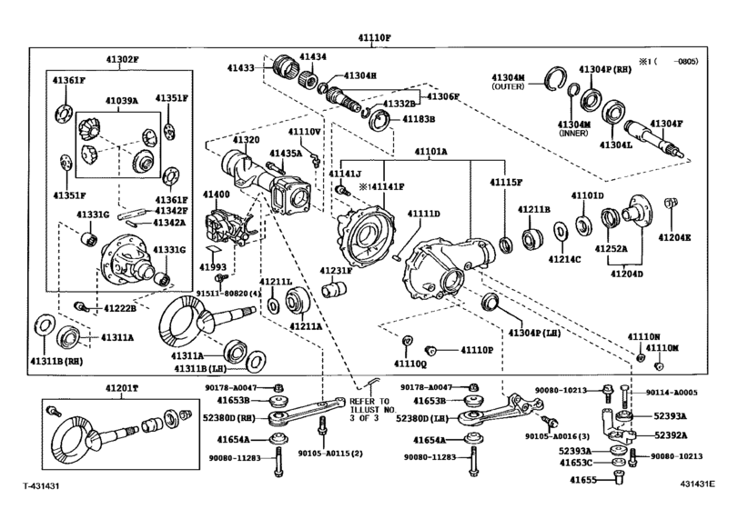
While specific diagrams may vary slightly depending on the Tacoma's year and model (e.g., 2nd gen vs. 3rd gen, ADD vs. non-ADD), the core components remain largely the same. Here's a rundown of the main parts you'll typically see in a front differential diagram:
- Differential Housing: The main casing that encloses all the internal components.
- Ring Gear: A large, circular gear bolted to the differential carrier. It receives power from the pinion gear.
- Pinion Gear: A smaller gear that meshes with the ring gear. It's driven by the front driveshaft.
- Differential Carrier (Case): Holds the spider gears and side gears. It rotates with the ring gear.
- Side Gears (Axle Gears): Splined to the axle shafts, transmitting power to the wheels.
- Spider Gears (Pinion Gears): Small gears that rotate within the carrier, allowing the wheels to turn at different speeds during turns. This is the key function of the differential.
- Axle Shafts: Connect to the side gears and transmit power to the wheels.
- Bearings: Support the ring gear, pinion gear, and differential carrier, allowing them to rotate smoothly. Common bearings include pinion bearings (inner and outer) and carrier bearings.
- Seals: Prevent oil leaks. The pinion seal and axle seals are common failure points.
- Crush Sleeve (Pinion Spacer): A collapsible spacer used to set pinion bearing preload. It's critical for proper operation.
- Automatic Disconnecting Differential (ADD) components (if applicable): This includes the ADD actuator, shift fork, and sleeve that engages/disengages the passenger-side axle.
Important Specs: Gear ratio (e.g., 3.73, 4.10) is a crucial spec, as is the type of differential (e.g., open, limited-slip, locking). Bearing preload specifications are essential for proper assembly and longevity. Always consult your vehicle's service manual for specific torque values and preload settings.
Understanding Diagram Symbols
Diagrams use a variety of lines, colors, and icons to convey information. Here's a brief guide:
- Solid Lines: Typically represent physical connections between parts. A thick solid line might indicate a major component.
- Dashed Lines: Often indicate hidden components or lines of force/motion.
- Arrows: Show the direction of rotation or movement. For example, an arrow on the pinion gear indicates its direction of rotation.
- Cutaway Views: Diagrams often use cutaway views to show the internal workings of a component. These are usually shaded differently.
- Exploded Views: Show the components separated from each other, but in their relative positions. This is very helpful for understanding assembly order.
- Numbers/Labels: Each component is usually labeled with a number or letter that corresponds to a parts list or description.
- Colors: While not always present, colors can be used to differentiate materials or highlight specific parts. For example, oil passages might be colored blue.
Pay close attention to the legend or key that accompanies the diagram. It will explain the specific symbols used in that particular diagram.
How It Works
The front differential's primary function is to transmit power from the engine (via the transmission, transfer case, and front driveshaft) to the front wheels. It also allows the front wheels to rotate at different speeds during turns. Here's a simplified explanation:
- The front driveshaft rotates the pinion gear.
- The pinion gear meshes with the ring gear, causing the ring gear to rotate.
- The ring gear is bolted to the differential carrier.
- The differential carrier houses the side gears and spider gears.
- When the vehicle is traveling straight, the spider gears don't rotate relative to the carrier. Both axle shafts (connected to the side gears) rotate at the same speed.
- During a turn, the spider gears rotate, allowing the outer wheel to rotate faster than the inner wheel. This prevents binding and tire wear.
- In the case of an ADD system, the actuator engages or disengages the passenger-side axle, effectively connecting or disconnecting that wheel from the differential. This is done for fuel efficiency in 2WD mode.
The gear ratio of the ring and pinion gears determines the final drive ratio. A lower gear ratio (e.g., 4.88) provides more torque but lower top speed, while a higher gear ratio (e.g., 3.73) provides less torque but higher top speed.
Real-World Use: Basic Troubleshooting
Here are a few common issues you might encounter and how the diagram can help:
- Whining Noise: Could indicate worn pinion bearings or ring and pinion gears. Use the diagram to locate these components and inspect them for wear.
- Clunking Noise: Could indicate worn spider gears, side gears, or excessive backlash. The diagram will help you identify these parts.
- Oil Leak: Common leak points include the pinion seal and axle seals. The diagram shows the location of these seals.
- ADD System Malfunction (if applicable): If the ADD system isn't engaging/disengaging properly, the diagram can help you trace the components involved, including the actuator, shift fork, and sleeve.
Troubleshooting Tip: Always start by checking the differential fluid level. Low fluid can cause significant damage. Refer to the diagram to locate the fill and drain plugs.
Safety First!
Working on a differential can be dangerous. Here are some key safety precautions:
- Always wear safety glasses and gloves. Gear oil can be messy and harmful.
- Use jack stands to support the vehicle securely. Never work under a vehicle supported only by a jack.
- Be careful when handling heavy components. The differential housing and ring gear can be quite heavy.
- The crush sleeve is a critical component. Improper installation can lead to premature bearing failure. Always use a new crush sleeve and follow the manufacturer's instructions carefully.
- Work in a well-ventilated area. Some cleaning solvents and gear oils can emit harmful fumes.
- Disconnect the battery. Although unlikely, accidentally shorting something could cause damage or injury.
- If you're not comfortable with any aspect of the repair, consult a qualified mechanic. It's better to be safe than sorry.
Warning: Improper differential work can lead to catastrophic failure, potentially causing an accident. If you're unsure about any step, seek professional assistance.
Hopefully, this article has provided you with a solid understanding of the Toyota Tacoma front differential diagram. Remember to consult your vehicle's service manual for specific instructions and torque specifications. Happy wrenching!
We have a detailed front differential diagram file available for download. Contact us through the website's contact form to get access to the file and further enhance your understanding. We're here to support your DIY endeavors.