
Tractor Trailer Air Brake System Diagram
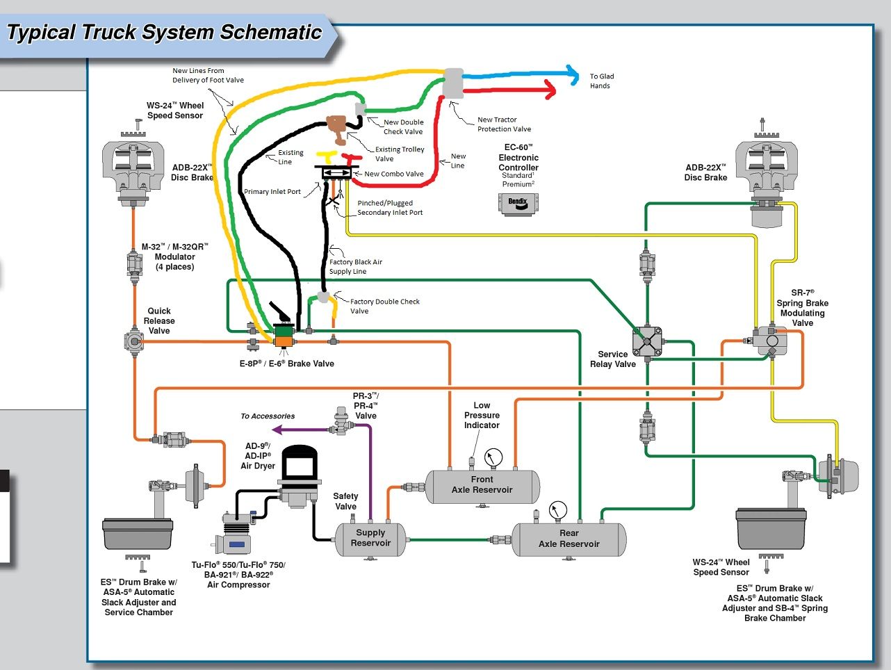
Alright, let's dive into the fascinating world of tractor-trailer air brake systems. This isn't your grandpa's hydraulic setup. These systems are beefy, complex, and absolutely critical for safety when hauling massive loads. Understanding the diagram for this system is paramount, whether you're a seasoned mechanic, a serious DIYer looking to expand your skills, or just someone who wants to know how these behemoths stop.
Why This Diagram Matters
Think of the air brake system diagram as the roadmap to a vital piece of your equipment. Knowing how the system is designed and built is fundamental for several reasons:
- Repair and Maintenance: Diagnosing issues becomes much easier when you can trace the air lines, identify components, and understand the flow of air. The diagram lets you pinpoint the source of a leak or a malfunctioning valve, potentially saving hours of guesswork.
- Modification and Customization: Want to add an auxiliary air tank for additional braking power? Or perhaps install a trailer brake controller? The diagram is your blueprint, ensuring compatibility and safe integration.
- Learning the Fundamentals: Even if you never plan on wrenching on a semi-truck, understanding the principles behind air brakes offers a profound appreciation for engineering and safety. It's a complex, robust system designed to withstand extreme conditions.
- Pre-Trip Inspections: Familiarity with the diagram makes your pre-trip inspections more thorough. You'll know where to look for potential problems, such as cracked lines or leaking fittings.
Key Specs and Main Parts
Before we delve into the diagram symbols, let's identify the core components of a typical tractor-trailer air brake system.
- Air Compressor: This engine-driven pump creates the compressed air that powers the entire system. Typical operating pressure is between 100 and 125 PSI.
- Air Governor: The brain of the system, the governor regulates the air compressor, maintaining the desired pressure range. When the pressure reaches the upper limit, the governor unloads the compressor. When pressure falls below the lower limit, the governor allows it to build pressure again.
- Air Tanks (Reservoirs): These tanks store the compressed air, providing a ready supply for braking and other functions. Tractors and trailers typically have multiple tanks.
- Brake Valves:
- Foot Valve (Service Brake Valve): Controlled by the brake pedal, this valve meters the amount of air pressure sent to the brakes.
- Tractor Protection Valve: This valve protects the tractor's air supply in case of a trailer breakaway. If the trailer's air lines are severed, this valve automatically closes, preventing the tractor from losing all air pressure.
- Relay Valve: Positioned closer to the rear brakes, relay valves speed up brake application and release by reducing the distance the air has to travel.
- Parking Brake Valve (Spring Brake Valve): Controls the spring brakes, which are mechanically applied by powerful springs. Air pressure is used to hold the springs *off*. Losing air pressure automatically applies the spring brakes.
- Brake Chambers: These devices convert air pressure into mechanical force, which applies the brakes. There are typically two types:
- Service Brake Chambers: Applied by the foot valve.
- Spring Brake Chambers: Include a spring brake section for parking and emergency braking.
- Slack Adjusters: These devices connect the brake chamber pushrod to the brake camshaft. They adjust the brake shoe clearance to compensate for brake lining wear.
- Brake Shoes/Pads and Drums/Rotors: The friction materials that actually stop the wheels.
- Air Lines and Fittings: These connect all the components, carrying the compressed air throughout the system.
- Automatic Slack Adjusters (ASA): Maintain the correct brake stroke by automatically adjusting for brake lining wear. (Note: manual slack adjusters require periodic manual adjustment).
- Anti-lock Braking System (ABS): A computer controlled system to prevent wheel lockup during braking.
Diagram Symbols
Understanding the symbols used in the air brake system diagram is crucial for interpreting it correctly.
- Lines:
- Solid Lines: Typically represent the main air lines carrying compressed air.
- Dashed Lines: Often indicate control lines, which carry signals to valves or other components.
- Double Lines: Sometimes used to represent mechanical linkages or connections.
- Colors: Color coding can vary between manufacturers, but some common conventions exist. For example:
- Red: Often used for the supply line from the air compressor.
- Green: Can represent the service brake line.
- Yellow: Frequently used for the parking brake line.
- Icons: Each component has a standardized symbol. Some common examples include:
- Air Tank: A cylindrical shape.
- Air Compressor: A pump symbol.
- Valve: A combination of squares and triangles indicating flow direction.
- Brake Chamber: A circular shape with a piston symbol.
How It Works
Here's a simplified overview of how the air brake system functions:
- The air compressor, driven by the engine, constantly pumps air into the air tanks.
- The governor monitors the air pressure and unloads the compressor when the desired pressure is reached.
- When the driver presses the brake pedal (foot valve), the valve meters the amount of compressed air sent to the brake chambers.
- The air pressure in the brake chambers pushes on a pushrod, which rotates the slack adjuster and applies the brakes.
- Releasing the brake pedal vents the air from the brake chambers, releasing the brakes.
- The spring brakes are held *off* by air pressure. When the parking brake valve is activated (or air pressure is lost), the springs apply the brakes mechanically.
- The tractor protection valve automatically seals off the tractor's air supply if the trailer breaks away or loses air pressure, preventing a complete loss of braking power.
Real-World Use: Basic Troubleshooting Tips
Here are a few common problems you might encounter and how the diagram can help you diagnose them:
- Low Air Pressure: Consult the diagram to trace the air lines from the compressor to the tanks. Look for leaks at fittings, hoses, and valves. Check the governor's operation.
- Slow Brake Application or Release: The diagram can help you identify relay valves and ensure they are functioning correctly. Check for restrictions in the air lines.
- Uneven Braking: Use the diagram to verify that all brake chambers are receiving equal air pressure. Inspect slack adjusters for proper adjustment.
- Air Leaks: The most common issue. Listen carefully and use soapy water to locate leaks at fittings, hoses, and valves. The diagram shows you the vulnerable spots.
- Spring Brakes Not Releasing: Check the air supply to the spring brake chambers. Consult the diagram to identify the parking brake valve and ensure it's functioning correctly. A frozen relay valve could also be the culprit.
Safety
Working on air brake systems can be dangerous. Here are some crucial safety precautions:
- Depressurize the System: Always drain the air tanks before working on any part of the system. A sudden release of compressed air can cause serious injury.
- Support the Vehicle: Never rely solely on the air brakes to hold a vehicle in place. Use jack stands or other appropriate supports.
- Wear Safety Glasses: Protect your eyes from debris and flying particles.
- Proper Training: Air brake systems are complex. If you're not comfortable working on them, seek professional assistance.
- Beware of Spring Brakes: The spring brakes contain powerful springs that can cause serious injury if released unexpectedly. Always ensure they are fully caged (held off) before removing any brake components.
Important Note: The spring brake chambers contain very strong springs that are under extreme tension. Incorrect handling can lead to serious injury or even death. Seek professional assistance if you are unfamiliar with these components.
This information is intended for educational purposes only and should not be considered a substitute for professional advice. Always consult a qualified mechanic for any repairs or modifications to your vehicle.
We have a detailed air brake system diagram file available for you to download. This diagram contains specific part numbers and details that can assist you with your repair or maintenance projects. Please reach out, and we'll get it sent over.