Trailblazer Front Suspension Diagram
Understanding Your Trailblazer's Front Suspension: A Deep Dive
For the seasoned DIY enthusiast or aspiring mechanic, understanding your vehicle's suspension system is crucial. This article focuses on the front suspension of the Chevrolet Trailblazer (and similar GM platforms). We'll break down a detailed diagram, explaining its purpose, key components, and how it all works together. Whether you're tackling a repair, considering modifications, or simply want a better grasp of your vehicle's mechanics, this guide will provide valuable insights.
Why Study the Diagram?
A front suspension diagram is more than just a pretty picture; it's a roadmap to understanding, diagnosing, and repairing one of your vehicle's most critical systems. Here’s why it matters:
- Troubleshooting: Pinpoint the source of noises, vibrations, or handling issues.
- Repairs: Identify parts needing replacement and understand their location within the system.
- Modifications: Plan and execute suspension upgrades with confidence, knowing how each component interacts.
- Preventative Maintenance: Spot potential problems before they become major headaches, saving you time and money.
- Learning: Gain a deeper understanding of automotive engineering principles.
Key Specs and Main Parts
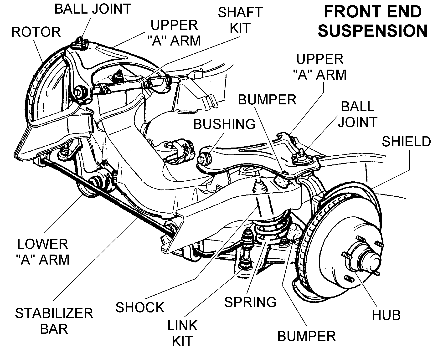
The Trailblazer (and many similar GM SUVs) typically utilize an independent front suspension system, usually a coil-over-shock configuration. This design allows each wheel to react independently to road conditions, improving ride quality and handling. Here's a breakdown of the key components often represented in a diagram:
- Upper and Lower Control Arms: These are hinged suspension members that connect the wheel hub/spindle to the vehicle's frame. They control the wheel's vertical movement. The upper control arm is often shorter than the lower.
- Coil Springs: The primary energy-absorbing component, supporting the vehicle's weight and absorbing bumps.
- Shock Absorbers (Dampers): These control the oscillation of the coil springs, preventing excessive bouncing and maintaining tire contact with the road. They work by forcing hydraulic fluid through small orifices, creating resistance.
- Steering Knuckle (Spindle): This is the pivoting point that holds the wheel bearing, hub, and brake assembly. It connects to the control arms via ball joints.
- Ball Joints: Spherical bearings that allow for movement between the control arms and the steering knuckle. They are crucial for steering and suspension articulation.
- Sway Bar (Stabilizer Bar): A torsion spring that connects the left and right sides of the suspension. It reduces body roll during cornering by transferring force from one side of the suspension to the other.
- Sway Bar End Links: Connect the sway bar to the control arms or struts.
- Wheel Hub/Bearing Assembly: Allows the wheel to rotate freely. Contains bearings that are typically sealed.
- Tie Rods (Inner and Outer): Part of the steering linkage, connecting the steering rack to the steering knuckle. Transmits steering input to turn the wheels.
- Bump Stops: Cushions that prevent the suspension from bottoming out on large impacts.
Understanding Diagram Symbols
Suspension diagrams use a variety of lines, colors, and icons to represent different components and connections. Here’s a general guide, though specific diagrams may have slight variations:
- Solid Lines: Typically represent physical components, such as control arms, springs, and shocks. Thicker lines might indicate major structural parts.
- Dashed Lines: Often indicate hidden or less-critical components, such as fasteners or wiring harnesses.
- Colors: While not standardized across all diagrams, colors might be used to differentiate systems (e.g., blue for hydraulics, green for grounding).
- Arrows: Indicate direction of movement or force, such as the travel of the suspension or the flow of hydraulic fluid.
- Fastener Symbols: Represent bolts, nuts, and other fasteners. These may be accompanied by torque specifications in the diagram or associated documentation.
- Component Icons: Simplified drawings of the components themselves, making it easier to identify them. A spring is usually represented by a coiled line, a shock absorber by a cylinder with a piston, and so on.
How It Works: The Suspension in Action
The Trailblazer's front suspension is designed to provide a smooth and controlled ride while maintaining good handling. Here's a simplified explanation of how it functions:
- Impact Absorption: When the wheel encounters a bump, the coil spring compresses, absorbing the energy.
- Damping: The shock absorber dampens the spring's oscillations, preventing the vehicle from bouncing excessively.
- Wheel Movement: The upper and lower control arms allow the wheel to move up and down while maintaining a relatively constant wheel alignment.
- Steering: The steering knuckle pivots on the ball joints, allowing the wheels to be steered left and right via the tie rods.
- Stabilization: The sway bar resists body roll during cornering, improving stability.
Real-World Use: Basic Troubleshooting
A suspension diagram can be invaluable for troubleshooting. Here are some common issues and how the diagram can help:
- Clunking Noise: Could indicate worn ball joints, sway bar end links, or shock absorbers. The diagram helps you locate and inspect these components.
- Bouncing Ride: Likely a sign of worn shock absorbers. The diagram pinpoints their location for inspection and replacement.
- Poor Handling: Could be caused by worn ball joints, tie rod ends, or damaged control arm bushings. The diagram helps you identify and assess these parts.
- Uneven Tire Wear: Might indicate misalignment, worn suspension components, or bent parts. The diagram can assist in identifying damaged or worn components contributing to misalignment.
Safety First!
Working on suspension components can be dangerous. Always take the following precautions:
- Use Jack Stands: Never work under a vehicle supported only by a jack. Always use properly rated jack stands.
- Compress Springs Safely: Coil springs store a tremendous amount of energy. Use a proper spring compressor to avoid serious injury. Consider having a professional handle spring compression if you are not experienced.
- Disconnect the Battery: Prevents accidental starting of the engine or activation of electrical components.
- Wear Safety Glasses: Protect your eyes from flying debris.
- Refer to the Service Manual: Always consult the vehicle's service manual for specific instructions and torque specifications.
- Ball Joints and Tie Rods: Be extremely cautious when disconnecting these components. They can separate suddenly and with force.
Accessing the Diagram
We have a detailed, high-resolution front suspension diagram available for download. It includes exploded views and component callouts to assist you in your repairs or modifications. This resource is designed to complement this article, giving you visual references as you delve deeper into your Trailblazer's front suspension system.