
Trailblazer Vortec 4200 Engine Diagram
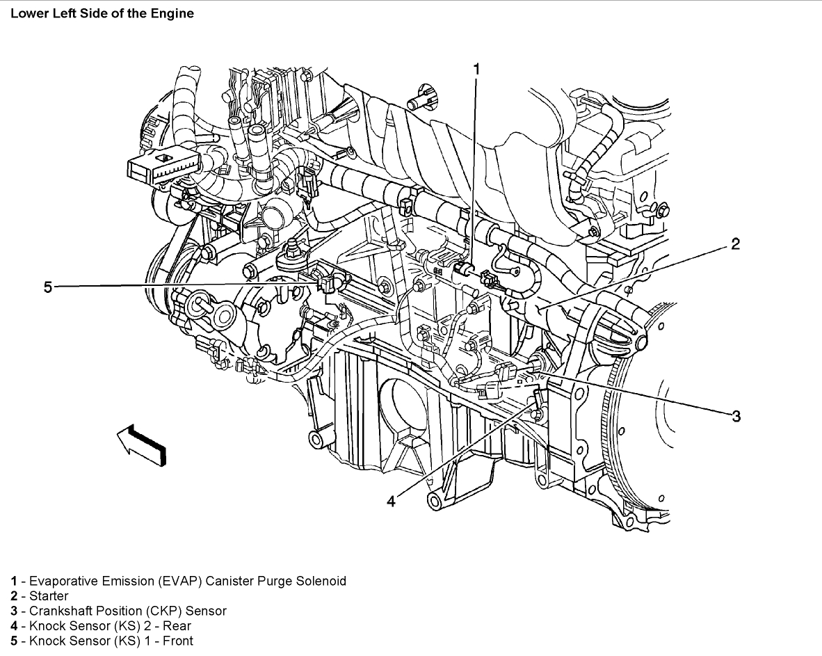
So, you're diving into the world of the GM Vortec 4200 engine, specifically as found in the Chevy Trailblazer. Excellent choice! This inline-six is a workhorse, but like any engine, understanding its intricacies is key for successful repairs, modifications, or even just preventive maintenance. That's where a detailed engine diagram comes in. This article will act as your comprehensive guide, breaking down the Trailblazer Vortec 4200 engine diagram, its purpose, key components, and how to use it effectively.
Why This Diagram Matters
The engine diagram isn’t just a pretty picture; it's your roadmap for understanding the engine's architecture and the relationships between its components. Here's why it's crucial:
- Diagnostic Aid: Quickly pinpoint the location of sensors, actuators, and other components when troubleshooting issues. Forget spending hours hunting for the crankshaft position sensor – the diagram shows you exactly where it lives.
- Repair Guidance: Before tackling any repair, the diagram provides a visual reference. It helps you understand the disassembly and reassembly process, reducing the risk of errors.
- Modification Planning: Considering performance upgrades? The diagram allows you to understand how aftermarket parts will integrate with the existing system. Want to add an aftermarket air intake? See how it connects to the throttle body and MAF sensor.
- Preventive Maintenance: Regularly reviewing the diagram can remind you of maintenance points you might otherwise overlook, such as the location of coolant drain plugs or specific vacuum lines.
- Educational Tool: For anyone eager to learn more about engine technology, the diagram provides a detailed visual representation of the engine's internal workings.
Key Specs and Main Parts of the Vortec 4200
Before we dive into the diagram itself, let's cover some essential specs and components. This will give you context when interpreting what you see on the diagram.
Specifications:
- Engine Type: Inline-Six, DOHC (Dual Overhead Camshaft)
- Displacement: 4.2 Liters (256 Cubic Inches)
- Bore x Stroke: 93 mm x 102 mm (3.66 in x 4.02 in)
- Compression Ratio: 10:1
- Horsepower: Around 270-291 hp (depending on the year and model)
- Torque: Around 275-277 lb-ft (depending on the year and model)
- Fuel System: Sequential Fuel Injection (SFI)
Main Components:
- Cylinder Head: Houses the valves, camshafts, and spark plugs. It's a critical component for controlling airflow and combustion.
- Engine Block: The foundation of the engine, containing the cylinders, pistons, and crankshaft.
- Crankshaft: Converts the linear motion of the pistons into rotational motion.
- Pistons: Move up and down within the cylinders, driven by combustion.
- Connecting Rods: Connect the pistons to the crankshaft.
- Camshafts: Control the opening and closing of the intake and exhaust valves. The Vortec 4200 uses dual overhead camshafts (DOHC) for precise valve timing.
- Valves (Intake & Exhaust): Control the flow of air and fuel into the cylinders and exhaust gases out.
- Intake Manifold: Distributes air to the cylinders.
- Exhaust Manifold: Collects exhaust gases from the cylinders.
- Throttle Body: Controls the amount of air entering the engine.
- Fuel Injectors: Spray fuel into the intake ports or directly into the cylinders.
- Spark Plugs: Ignite the air-fuel mixture in the cylinders.
- Ignition Coils: Provide the high voltage needed to fire the spark plugs. Each cylinder has its own coil in a coil-on-plug (COP) system.
- Sensors:
- Crankshaft Position Sensor (CKP): Monitors the position of the crankshaft.
- Camshaft Position Sensor (CMP): Monitors the position of the camshaft(s).
- Mass Airflow Sensor (MAF): Measures the amount of air entering the engine.
- Oxygen Sensors (O2): Monitor the oxygen content in the exhaust gas.
- Throttle Position Sensor (TPS): Measures the position of the throttle plate.
- Engine Coolant Temperature Sensor (ECT): Measures the engine coolant temperature.
- Cooling System: Consisting of the water pump, radiator, thermostat, and coolant hoses, it regulates the engine's temperature.
- Lubrication System: Consisting of the oil pump, oil filter, and oil passages, it provides lubrication to the engine's moving parts.
Understanding the Symbols
Engine diagrams use a variety of symbols to represent different components and connections. Here's a breakdown of the common ones you'll encounter on a Vortec 4200 diagram:
- Lines:
- Solid Lines: Typically represent fluid lines (coolant, oil, fuel) or mechanical linkages.
- Dashed Lines: Usually indicate vacuum lines or electrical wiring. Pay close attention to the specific type of dash, as different patterns can denote different types of wiring (e.g., shielded, unshielded).
- Dotted Lines: Can represent control signals or reference lines.
- Colors:
- Color Coding: Varies depending on the diagram's origin, but electrical wiring diagrams commonly use colors to identify different circuits. A legend should always be provided.
- Fluid Lines: May use colors to distinguish between different fluids (e.g., blue for coolant, red for oil).
- Icons:
- Circles: Often represent sensors, actuators, or electrical connectors.
- Squares/Rectangles: Can represent control modules or relays.
- Triangles: May indicate a specific type of valve or port.
- Engine symbol: Denotes the engine block itself.
- Abbreviations:
- ECU: Engine Control Unit
- PCM: Powertrain Control Module (effectively the same as the ECU in most modern vehicles)
- TCCM: Transfer Case Control Module (Relevant for 4x4 Trailblazers)
- MAF: Mass Airflow Sensor
- CKP: Crankshaft Position Sensor
- CMP: Camshaft Position Sensor
- ECT: Engine Coolant Temperature Sensor
Always refer to the diagram's legend for a complete explanation of the symbols used.
How the Vortec 4200 Works (Simplified)
The Vortec 4200 operates on the four-stroke combustion cycle: Intake, Compression, Combustion (Power), and Exhaust. Let's break down how the main systems contribute:
- Air Intake: Air enters through the air filter, passes through the MAF sensor (measuring air mass), and then through the throttle body (controlled by the accelerator pedal). The intake manifold distributes the air to each cylinder.
- Fuel Delivery: The fuel injectors spray fuel into the intake ports, mixing with the incoming air. The ECU controls the amount of fuel injected based on various sensor inputs (MAF, O2 sensors, etc.).
- Combustion: The spark plugs ignite the air-fuel mixture in each cylinder, creating a powerful explosion that pushes the pistons down.
- Exhaust: The exhaust gases are forced out of the cylinders through the exhaust valves, into the exhaust manifold, through the catalytic converter (to reduce emissions), and finally out the tailpipe.
- Cooling: The water pump circulates coolant through the engine block and cylinder head, absorbing heat. The coolant then flows through the radiator, where the heat is dissipated into the air.
- Lubrication: The oil pump circulates oil throughout the engine, lubricating the moving parts and reducing friction. The oil filter removes contaminants from the oil.
Real-World Use & Basic Troubleshooting
Let's say your Trailblazer is experiencing rough idling. Using the engine diagram, you can start your troubleshooting process:
- Vacuum Leaks: Check vacuum lines (especially around the intake manifold and throttle body) for cracks or disconnections. The diagram helps you locate all the vacuum line connections.
- MAF Sensor: Locate the MAF sensor on the diagram and then physically inspect it. Is it clean? Is the connector secure? A faulty MAF sensor can cause rough idling.
- Spark Plugs/Ignition Coils: The diagram will show the location of each spark plug and its corresponding ignition coil. A misfiring cylinder can cause rough idling, so inspect the plugs and coils for damage.
- Fuel Injectors: While harder to diagnose without specialized equipment, the diagram shows you where each injector is located. Listen for a clicking sound from each injector when the engine is running; silence may indicate a faulty injector.
Remember to always start with the simplest and most obvious potential causes before moving on to more complex diagnoses.
Safety First!
Working on an engine involves inherent risks. Pay special attention to the following:
- Fuel System: Fuel is highly flammable. Disconnect the fuel pump fuse or relay before working on any fuel system components. Always work in a well-ventilated area.
- Electrical System: Disconnect the negative battery cable before working on any electrical components. The ignition system carries high voltage and can deliver a dangerous shock.
- Cooling System: The cooling system is under pressure, and the coolant can be very hot. Allow the engine to cool completely before opening the radiator cap or disconnecting coolant hoses.
- Exhaust System: The exhaust system gets extremely hot. Allow it to cool completely before working on it.
- Moving Parts: Be aware of moving parts, such as the crankshaft, camshafts, and pulleys. Keep your hands and clothing clear of these parts when the engine is running.
Always wear appropriate safety gear, including safety glasses and gloves.
By understanding the Vortec 4200 engine diagram and using it in conjunction with a repair manual and some careful observation, you'll be well-equipped to tackle a wide range of repairs and maintenance tasks on your Trailblazer. Remember, taking your time and being thorough are key to success.
We have the file (the diagram) available for download. Please reach out, and we can provide you with the link!