Trailer Brake Control Wiring Diagram
Understanding the wiring diagram for your trailer brake controller is crucial whether you're tackling a repair, installing a new controller, or simply expanding your knowledge of your vehicle's electrical system. This article will walk you through the essential aspects of a typical trailer brake control wiring diagram, equipping you with the knowledge to confidently work with these systems. We'll break down the symbols, explain how it all functions, and offer some practical troubleshooting advice.
Why Understanding the Wiring Diagram Matters
A trailer brake controller wiring diagram is your roadmap to the electrical system that manages your trailer's brakes. It provides a visual representation of how the various components are connected and how they interact. This knowledge is essential for:
- Troubleshooting: Identifying the cause of brake controller malfunctions (e.g., no trailer brakes, weak braking, error codes).
- Installation: Correctly connecting a new or replacement brake controller to your tow vehicle.
- Repair: Fixing damaged wiring or faulty components in the brake control circuit.
- Customization: Modifying the system for specific needs (advanced users only).
- General Understanding: Gaining a deeper understanding of your vehicle's electrical systems.
Without a diagram, you're essentially working blind, increasing the risk of incorrect wiring, electrical damage, and potentially dangerous situations while towing.
Key Specifications and Main Parts of a Trailer Brake Controller System
Before diving into the diagram, let's review the key components you'll encounter:
- Brake Controller Unit: The brains of the system. It senses the tow vehicle's deceleration and sends a corresponding signal to the trailer brakes. Modern controllers are often proportional, meaning the braking force applied to the trailer is proportional to the deceleration of the tow vehicle. Older units may be time-delayed, which apply braking force based on a set time.
- Wiring Harness: A bundle of wires specifically designed for connecting the brake controller to the vehicle's electrical system and the trailer connector. Typically uses a 7-way RV blade connector for the trailer side.
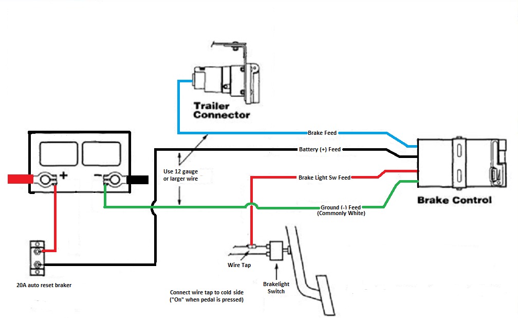
- 7-Way RV Blade Connector (Trailer Connector): This connector provides the electrical interface between the tow vehicle and the trailer. It carries signals for tail lights, brake lights, turn signals, auxiliary power, and, most importantly, the brake control signal.
- Brake Pedal Switch Wire (Cold Side): This wire connects to the brake light switch and signals the brake controller when the tow vehicle's brakes are applied. It's often referred to as the "cold side" of the switch because it only carries voltage when the brake pedal is depressed.
- Power Wire: Provides the 12V power source for the brake controller, usually directly from the vehicle's battery, often with a dedicated fuse.
- Ground Wire: Completes the electrical circuit, providing a return path for the current. A good, clean ground connection is critical for proper operation.
- Trailer Brake Output Wire: This wire carries the variable voltage signal from the brake controller to the trailer brakes.
- Fuses and Circuit Breakers: Protective devices that prevent damage to the electrical system in case of a short circuit or overload.
Decoding the Symbols: Lines, Colors, and Icons
Wiring diagrams use a standardized set of symbols to represent electrical components and connections. Understanding these symbols is crucial for interpreting the diagram accurately. Here's a breakdown of common symbols you'll encounter:
- Lines: Represent wires. Solid lines indicate a direct connection. Dashed lines might represent a shielded wire or a connection that's only active under certain conditions.
- Colors: Each wire in the harness is typically color-coded (e.g., red for power, black for ground, blue for trailer brake output). The diagram will indicate the color of each wire, which is essential for correct connections. Common colors include:
- Red: Power (12V+)
- Black: Ground
- Blue: Trailer Brake Output
- White: Ground (often used interchangeably with black)
- Brown: Right Turn/Brake Light
- Yellow: Left Turn/Brake Light
- Green: Tail Lights
- Icons: Represent specific components:
- Rectangle with a diagonal line: Resistor
- Circle with a plus and minus sign: Battery
- Circle with a wavy line: Fuse
- Ground Symbol (three horizontal lines decreasing in length): Indicates a ground connection to the vehicle chassis.
- Brake Light Switch: Symbol varies, but usually represents a switch that closes when the brake pedal is pressed.
Always refer to the specific wiring diagram for your vehicle and brake controller, as symbols and color codes can vary.
How It Works: The Flow of Electricity
The trailer brake controller system works by sensing the tow vehicle's deceleration and applying the trailer brakes proportionally. Here's a simplified explanation of the electrical flow:
- When the brake pedal is pressed, the brake light switch closes, sending a signal to the brake controller via the brake pedal switch wire.
- The brake controller, powered by the 12V power wire, detects this signal and activates its internal circuitry.
- Based on the deceleration rate (determined by the brake controller's internal sensors), the controller sends a variable voltage signal to the trailer brakes through the trailer brake output wire.
- This voltage signal activates the electromagnets in the trailer brake assemblies, which in turn apply friction to the brake drums or rotors, slowing the trailer.
- The ground wire completes the circuit, allowing the current to flow back to the vehicle's battery.
Real-World Use: Basic Troubleshooting Tips
Here are some common issues and troubleshooting tips based on the wiring diagram:
- No Trailer Brakes:
- Check the fuse on the power wire to the brake controller.
- Verify that the brake controller is properly grounded.
- Inspect the trailer brake output wire for damage or loose connections.
- Use a multimeter to test for voltage on the trailer brake output wire when the brake pedal is pressed. If no voltage is present, the brake controller may be faulty.
- Weak Trailer Brakes:
- Check the brake controller's gain setting. Increase the gain for more aggressive braking.
- Inspect the trailer brake wiring for corrosion or loose connections.
- Ensure the trailer brakes are properly adjusted.
- Brake Controller Displaying Error Codes:
- Consult the brake controller's manual to interpret the error code.
- Common error codes indicate short circuits, open circuits, or faulty brake controller components.
- Check all wiring connections for shorts to ground.
Always disconnect the battery before performing any electrical work to prevent accidental shorts or shocks.
Safety First: Highlighting Risky Components
Working with electrical systems can be dangerous. Here are some key safety considerations:
- Battery Power: The 12V battery system can deliver a significant electrical shock. Always disconnect the negative battery terminal before working on the electrical system.
- Fuses: Never replace a fuse with one of a higher amperage rating. Doing so can overload the circuit and cause a fire.
- Wiring Insulation: Damaged wiring insulation can expose bare wires, creating a shock hazard. Replace any damaged wiring immediately.
- Short Circuits: Avoid creating short circuits, which can damage the vehicle's electrical system. Double-check all wiring connections before reconnecting the battery.
If you're not comfortable working with electrical systems, consult a qualified mechanic.
With a solid understanding of the trailer brake control wiring diagram and the components involved, you'll be well-equipped to tackle repairs, installations, and troubleshooting tasks. Remember to always prioritize safety and consult the specific documentation for your vehicle and brake controller.
We have a sample trailer brake control wiring diagram file available for download. Understanding the diagram will become much easier when you use it in conjunction with the details provided in this article.