
Trailer Brake Controller Wiring Harness
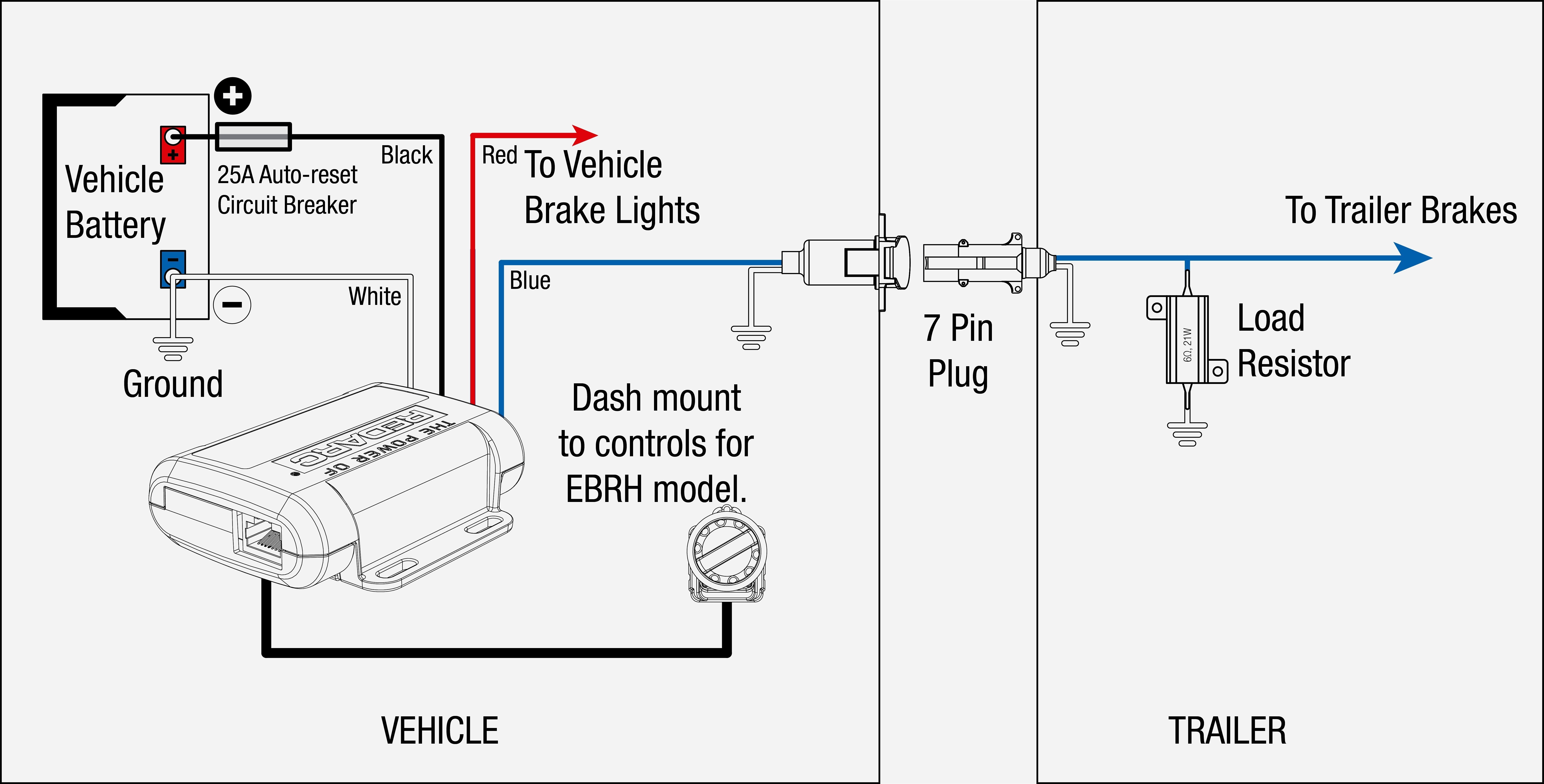
So, you're thinking about towing a trailer and need to get your electricals sorted? That's a smart move! Understanding your trailer brake controller wiring harness is absolutely crucial for safe and effective towing. Whether you're upgrading your existing setup, troubleshooting a faulty connection, or simply expanding your automotive knowledge, this guide will walk you through the intricacies of this often-overlooked but vital component.
Purpose: Why This Diagram Matters
Think of your trailer brake controller wiring harness as the nervous system connecting your tow vehicle's brain (the brake controller) to the muscles (the trailer brakes). A clear and accurate wiring diagram is your roadmap to a functioning system. It allows you to:
- Diagnose Issues: Trace faulty wiring, identify shorts, and pinpoint breaks in the circuit.
- Perform Repairs: Replace damaged wires, connectors, or the brake controller itself with confidence.
- Install a New Controller: Connect your new brake controller correctly the first time.
- Upgrade Existing Systems: Add features or improve the reliability of your towing setup.
- Understand the System: Gain a deeper knowledge of how your trailer brakes work in conjunction with your tow vehicle.
Key Specs and Main Parts
Before we dive into the diagram itself, let's cover the key components and their specifications.
Main Components:
- Brake Controller: The brains of the operation. This unit senses your tow vehicle's braking action and applies proportional braking force to the trailer brakes.
- Wiring Harness: The network of wires that carries the electrical signals between the brake controller, the tow vehicle's electrical system, and the trailer brakes.
- 7-Way Connector (or 4-Way): The standardized connector that plugs into the trailer, providing electrical connections for brakes, lights, and other accessories. 7-way is more common with brake controllers.
- Vehicle-Specific Connector (if applicable): Many modern vehicles come with a pre-wired connector specifically for brake controllers, simplifying installation.
- Fuses and Circuit Breakers: Protection devices that prevent overload and damage to the electrical system.
Key Specifications:
- Wire Gauge (AWG): The thickness of the wires, crucial for handling the amperage required by the trailer brakes. Typically, 10 or 12 AWG wire is used for the brake output circuit. Consult your brake controller's manual for specific recommendations.
- Voltage: Typically 12V DC, the standard voltage for automotive electrical systems.
- Amperage Rating: The maximum current the brake controller and wiring harness can handle. Exceeding this rating can lead to overheating and fire.
- Connector Type: The type of connector used to connect the brake controller to the vehicle's wiring harness. Common types include blade connectors, butt connectors, and vehicle-specific connectors.
Symbols: Understanding the Diagram
A wiring diagram uses symbols to represent electrical components and their connections. Here's a breakdown of common symbols you'll encounter:
- Lines: Represent wires. Thicker lines often indicate wires with a higher gauge (thicker wire).
- Dots: Indicate a wire connection. A dot where two or more lines intersect means they are electrically connected.
- Colors: Each wire is typically identified by a color code. Common colors include red (power), black (ground), blue (brake output), white (ground), brown (running lights), yellow (left turn/brake), and green (right turn/brake). Pay close attention to color codes as they are crucial for correct wiring.
- Rectangles: Often represent electrical components such as the brake controller, fuses, or relays.
- Circles: Can represent lights or other round components.
- Ground Symbol (typically three horizontal lines getting shorter): Indicates a connection to the vehicle's chassis ground.
- Fuse Symbol (squiggly line): Indicates a fuse. The amperage rating of the fuse is usually indicated next to the symbol.
- Battery Symbol (+/-): Indicates the vehicle's battery and its positive (+) and negative (-) terminals.
How It Works: The Electrical Flow
The trailer brake controller system works by sensing when you apply the brakes in your tow vehicle. When you press the brake pedal, the brake controller receives a signal from the vehicle's brake light circuit. Based on this signal, and often an inertia sensor inside the controller, the brake controller sends an electrical signal to the trailer brakes. This signal activates electromagnets within the trailer brake assemblies, which in turn apply pressure to the brake drums or rotors, slowing the trailer. The amount of braking force applied to the trailer is proportional to the braking force applied in the tow vehicle, ensuring smooth and controlled stopping.
The wiring harness facilitates this communication. The brake output wire (typically blue) carries the electrical signal from the brake controller to the trailer's electric brakes. A separate wire provides a ground connection, and other wires handle lighting signals such as turn signals, brake lights, and running lights.
Real-World Use: Basic Troubleshooting Tips
Encountering problems with your trailer brakes? Here are a few troubleshooting tips:
- No Trailer Brakes: Check the fuse for the brake controller. Verify the brake controller is properly grounded. Inspect the brake output wire (blue) for breaks or shorts. Test the trailer brake magnets for continuity.
- Weak Trailer Brakes: Adjust the gain setting on the brake controller. Check the trailer brake magnets for wear or damage. Inspect the brake controller wiring for corrosion or loose connections.
- Trailer Brakes Lock Up: Reduce the gain setting on the brake controller. Check for shorts in the brake output wire. Inspect the trailer brake magnets for damage.
- "Check Trailer Wiring" Message: Inspect all wiring connections between the tow vehicle and the trailer. Look for corrosion, loose connections, or damaged wires. Clean and tighten all connections.
- Lights Not Working: Check the fuses for the lighting circuits. Inspect the wiring for breaks or shorts. Test the trailer light bulbs.
Use a multimeter to test for voltage and continuity when troubleshooting electrical problems. This will help you pinpoint the exact location of the fault.
Safety: Highlight Risky Components
Working with electrical systems can be dangerous. Here are some key safety precautions:
- Disconnect the Battery: Always disconnect the negative terminal of the tow vehicle's battery before working on the electrical system.
- Use Proper Tools: Use insulated tools designed for automotive electrical work.
- Wear Safety Glasses: Protect your eyes from sparks and debris.
- Don't Overload Circuits: Ensure that the amperage rating of the brake controller and wiring harness is sufficient for the trailer brakes.
- Protect Wires: Use conduit or other protective coverings to protect wires from damage and abrasion.
- Fuses are Crucial: Never bypass or use an incorrect amperage fuse. Fuses are there to protect the system from dangerous overloads.
- Be Careful of Shorts: Short circuits can generate heat and cause fires. Inspect wiring carefully for potential shorts before connecting the battery.
- Double-Check Your Work: Before reconnecting the battery, double-check all wiring connections to ensure they are correct and secure.
The blue wire coming from the brake controller, carrying the brake signal, is a particularly sensitive wire. Damage here can cause complete brake failure on the trailer. Protect this wire carefully during installation and maintenance.
By following this guide and understanding the fundamentals of trailer brake controller wiring harnesses, you can confidently maintain and troubleshoot your towing electrical system, ensuring safe and reliable braking performance. Remember, safety always comes first!
We have a detailed wiring diagram available for download to further assist you. Contact us to receive the file.