
Trailer Electric Brakes Wiring Diagram
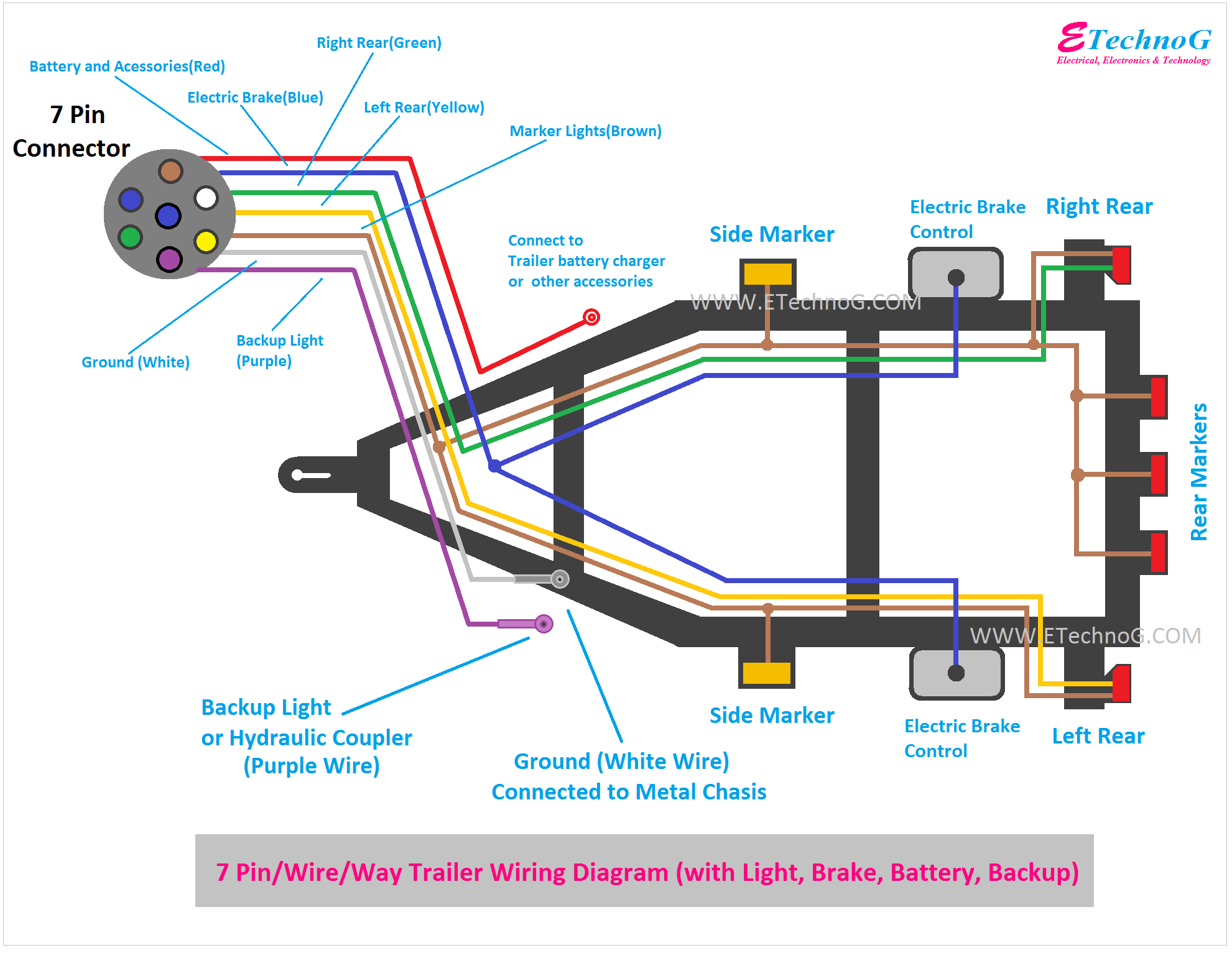
Understanding trailer electric brake wiring is crucial for safe towing and a necessity for any serious DIYer or mechanic. Whether you're diagnosing a malfunctioning brake system, adding electric brakes to a trailer, or simply deepening your knowledge of trailer electrical systems, a clear understanding of the wiring diagram is paramount. This guide will walk you through the key components, explain the diagram's symbolism, and provide troubleshooting tips to keep your trailer braking system in top condition. And, of course, we have the wiring diagram file available for you to download and reference while you work!
Why Understand Trailer Electric Brake Wiring?
A functional trailer brake system isn't just a good idea – it's often the law. Many jurisdictions require electric brakes on trailers exceeding a certain weight (typically 3,000 lbs gross trailer weight (GTWR) or more, but check your local regulations). Beyond legal requirements, properly functioning trailer brakes significantly improve safety by reducing stopping distances, minimizing sway, and preventing the tow vehicle's brakes from being overloaded.
Having a solid grasp of the wiring diagram allows you to:
- Diagnose and repair brake system issues efficiently.
- Install electric brakes on a trailer correctly.
- Modify your trailer's wiring for additional features.
- Ensure compliance with safety regulations.
- Avoid costly trips to a mechanic.
Key Specs and Main Parts
Trailer electric brake systems rely on a few key components, all interconnected via the wiring harness. Knowing these parts is essential for understanding the wiring diagram.
- 7-Way Connector (or 6-Way): This is the interface between your tow vehicle and the trailer. It carries signals for brake lights, turn signals, running lights, auxiliary power, and, most importantly, the brake control signal and ground. The 7-way is the most common and preferred connector for trailers with electric brakes because of the dedicated auxiliary power pin.
- Electric Brake Controller: Located in the tow vehicle, the brake controller sends a variable voltage signal to the trailer brakes, proportional to the braking force applied by the driver. Modern controllers often use inertia sensors or proportional technology to apply the brakes smoothly and effectively.
- Wiring Harness: This is the network of wires connecting all the components. It must be of adequate gauge (thickness) to handle the current demands of the electric brakes. Typically, a 12 or 10 gauge wire is used for the brake circuit.
- Electric Brake Assemblies: These are located inside the trailer's brake drums or rotors. They consist of an electromagnet, brake shoes, and associated hardware. When energized, the electromagnet pulls on an actuator arm, applying the brakes.
- Junction Box (Optional): Some trailers have a junction box where all the wiring from the 7-way connector is distributed to the various circuits. This simplifies wiring and troubleshooting.
- Grounding Points: Proper grounding is critical for a reliable electric brake system. All components must be well-grounded to the trailer frame.
Understanding the Wiring Diagram Symbols
Wiring diagrams use standardized symbols to represent components and connections. Here's a breakdown of common symbols you'll encounter in a trailer electric brake wiring diagram:
- Solid Lines: Represent wires. The thickness of the line may sometimes indicate the wire gauge (though this is not always the case).
- Dashed Lines: Often indicate grounds or less critical connections.
- Circles with Numbers: Indicate terminals or connection points. The numbers may correspond to pin numbers on the 7-way connector or other components.
- Rectangles: Represent electrical components like the brake controller, junction boxes, or relays.
- Coils: Represent electromagnets in the brake assemblies.
- Color Codes: Wires are typically color-coded to help identify their function. Common color codes include:
- Black: 12V Power
- White: Ground
- Blue: Brake Control Signal
- Brown: Right Turn/Brake Lights
- Green: Left Turn/Brake Lights
- Yellow: Running Lights
- Red: Auxiliary Power (often for battery charging or interior lights)
Important Note: Wire color codes can vary depending on the manufacturer. Always double-check the wiring diagram for your specific trailer or tow vehicle.
How It Works: The Electrical Flow
The electric brake system operates as follows:
- When the driver applies the brakes in the tow vehicle, the brake controller senses this and sends a voltage signal through the blue wire of the 7-way connector.
- This signal travels through the trailer's wiring harness to the electric brake assemblies at each wheel.
- The voltage energizes the electromagnet inside the brake assembly.
- The electromagnet pulls on an actuator arm (often called a brake lever or armature).
- The actuator arm applies pressure to the brake shoes, forcing them against the inside of the brake drum (or the brake pads against the rotor).
- The friction between the brake shoes/pads and the drum/rotor slows the trailer wheels.
- The amount of braking force applied is proportional to the voltage signal from the brake controller. The harder the driver presses the brakes, the higher the voltage, and the stronger the braking force on the trailer.
- Proper grounding ensures that the electrical circuit is completed, allowing current to flow freely and the brakes to function correctly.
Real-World Use: Basic Troubleshooting Tips
Here are some common issues you might encounter and how a wiring diagram can help you troubleshoot them:
- No Trailer Brakes:
- Check the 7-way connector: Ensure the pins are clean and making good contact. Use a multimeter to test for voltage on the brake control pin (blue wire) when the brakes are applied in the tow vehicle.
- Inspect the wiring harness: Look for damaged or corroded wires. Pay close attention to areas where the wiring is exposed or subject to abrasion.
- Test the brake controller: Use a multimeter to verify that the brake controller is sending a signal when the brakes are applied.
- Check the grounds: Ensure that all grounding points are clean, secure, and free of corrosion. Use a wire brush to clean grounding surfaces.
- Inspect the brake assemblies: Disconnect the wires from the brake assemblies and use a multimeter to test for continuity through the electromagnet. If there is no continuity, the electromagnet is likely faulty.
- Weak Trailer Brakes:
- Adjust the brake controller: Increase the gain setting on the brake controller to apply more braking force.
- Check the brake shoes/pads: Ensure that the brake shoes or pads are not worn or contaminated.
- Inspect the brake drums/rotors: Check for damage or excessive wear.
- Verify voltage: Ensure adequate voltage is reaching each brake assembly when braking.
- One Brake Not Working:
- Isolate the problem: Check the wiring and connections to that specific brake assembly.
- Test the electromagnet: Disconnect the wires from the faulty brake assembly and test for continuity.
- Brakes Locking Up:
- Reduce the gain: Decrease the gain setting on the brake controller.
- Check for shorts: Inspect the wiring harness for any shorts to ground.
- Inspect brake assembly: Check for mechanical binding preventing the brake from releasing.
Safety First!
Working with electrical systems can be dangerous. Always take the following precautions:
- Disconnect the power: Before working on any wiring, disconnect the trailer from the tow vehicle and disconnect the tow vehicle’s battery negative terminal.
- Use proper tools: Use insulated tools designed for electrical work.
- Wear safety glasses: Protect your eyes from flying debris or sparks.
- Be aware of your surroundings: Work in a well-lit and dry environment.
- Never work alone: Have someone nearby in case of an emergency.
- Special Caution: Be especially careful around the brake controller, as it contains electronic components that can be damaged by static electricity. Ground yourself before touching the controller.
By understanding the trailer electric brake wiring diagram and following these safety tips, you can confidently diagnose and repair brake system issues, ensuring safe and reliable towing. Remember, we have the wiring diagram file ready for you to download. Consult the diagram frequently during your work to ensure proper connections and avoid costly mistakes. Happy (and safe) wrenching!