Trailer Electrical Connector Wiring Diagram
Understanding trailer electrical connector wiring is crucial for any DIY mechanic, modder, or intermediate car owner who wants to tow safely and legally. This article breaks down the complexities of trailer wiring diagrams, providing you with the knowledge to diagnose issues, make repairs, and even perform custom installations. Whether you're dealing with faulty lights, a malfunctioning brake controller, or simply want to expand your understanding of automotive electrical systems, mastering the wiring diagram is your first step.
Purpose of a Trailer Electrical Connector Wiring Diagram
Why bother with a wiring diagram? There are several key reasons:
- Troubleshooting: When trailer lights fail (brake lights, turn signals, running lights), the diagram helps you trace the circuit, identify faulty components (like shorts or opens), and pinpoint the problem's source.
- Repairs: Once you've diagnosed the issue, the diagram shows you exactly where to reconnect wires, replace damaged connectors, or splice in new sections.
- New Installations: Installing a trailer hitch and wiring harness requires precise connections. The diagram ensures you wire everything correctly the first time, avoiding costly mistakes and potential safety hazards.
- Customization: Want to add auxiliary lights, a trailer brake controller, or other accessories? The diagram is your roadmap for integrating these components seamlessly into the existing electrical system.
- Understanding: Simply put, studying the wiring diagram enhances your overall understanding of how trailer electrical systems work. This knowledge empowers you to handle future issues with confidence.
Key Specs and Main Parts
Before diving into the diagram itself, let's define some key specifications and components. The most common trailer connectors are the 4-way flat, 5-way flat, 6-way round, and 7-way round (also known as a Bargman connector). Each connector offers a different set of functions. Here’s a breakdown:
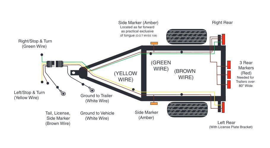
- 4-Way Flat: This is the most basic connector, providing connections for:
- Ground
- Tail lights (running lights)
- Left turn/brake light
- Right turn/brake light
- 5-Way Flat: Adds a wire for trailer brakes (typically blue). Often used for boat trailers with surge brakes.
- 6-Way Round: Typically used for older trailers and offers a wider range of functions, sometimes including battery power. Wiring configuration can vary significantly.
- 7-Way Round (Bargman): The most common connector for larger trailers, especially those with electric brakes and auxiliary power. Functions include:
- Ground
- Tail lights (running lights)
- Left turn signal
- Right turn signal
- Electric brakes
- Reverse lights
- 12V power (auxiliary)
Other important terms include:
- Gauge (AWG): Wire thickness. Higher AWG numbers indicate thinner wires. Trailer wiring typically uses 12-16 AWG.
- Voltage: The electrical potential, typically 12V DC in automotive applications.
- Amperage (Amps): The amount of electrical current flowing through a circuit.
- Continuity: A complete and uninterrupted electrical path.
- Ground: The reference point for all electrical circuits, typically connected to the vehicle's chassis.
- Short Circuit: An unintended low-resistance path that allows excessive current to flow, potentially causing damage.
- Open Circuit: A break in the electrical path, preventing current from flowing.
Understanding Symbols in Trailer Wiring Diagrams
A trailer wiring diagram uses standardized symbols to represent different components and connections. Learning these symbols is crucial for interpreting the diagram correctly.
- Lines: Solid lines represent wires. Dashed lines may represent a wire harness containing multiple wires. The thickness of the line doesn't necessarily correspond to wire gauge.
- Colors: Wires are typically identified by color codes (e.g., WH for white, BK for black, BR for brown, YL for yellow, GR for green, RD for red, BU for blue, OR for orange). These colors are standardized to some extent, but variations can exist. Always double-check with a multimeter.
- Ground Symbol: Typically represented by three horizontal lines decreasing in length, connected to a vertical line, indicating a connection to the vehicle's chassis.
- Connector Symbol: Usually depicted as a circle or rectangle with pins or sockets, representing the physical connector.
- Light Bulb Symbol: A circle with a cross inside, representing a light bulb.
- Resistor Symbol: A zigzag line, representing a component that restricts current flow.
- Fuse Symbol: A wavy line or a rectangle with a diagonal line, representing a fuse that protects the circuit from overcurrent.
- Switch Symbol: Depicts a switch that opens or closes a circuit.
- Splice Symbol: A dot where two or more wires connect. Note: Not all diagrams show splices explicitly.
The diagram will also show the specific pin assignments for each connector type. For example, in a 7-way round connector, pin 1 might be ground, pin 2 might be tail lights, and so on.
How It Works: Tracing the Circuit
The key to understanding a wiring diagram is to trace the electrical path from the vehicle's battery to the trailer lights and back. Let's consider a simplified example of a 4-way flat connector:
- Power Source: The vehicle's battery provides the power.
- Wiring Harness: Wires run from the vehicle's taillight assembly to a connector (often a T-connector that plugs into the existing wiring).
- Connector: The connector links the vehicle's wiring to the trailer's wiring.
- Trailer Wiring: Wires run from the connector along the trailer frame to the various lights.
- Lights: The tail lights, brake lights, and turn signals receive power.
- Ground: Each light is grounded to the trailer frame, which is then grounded to the vehicle through the connector.
When you activate the turn signal in the vehicle, the corresponding wire in the trailer harness receives power. This power flows to the turn signal light on the trailer, causing it to illuminate. Similarly, pressing the brake pedal sends power to the brake light wires, illuminating the trailer's brake lights. The ground wire provides the return path for the current to flow back to the vehicle's battery, completing the circuit. A break in any part of this circuit will cause the lights to malfunction.
Real-World Use: Basic Troubleshooting Tips
Using a wiring diagram during troubleshooting can save you time and frustration. Here are a few tips:
- Start with the obvious: Check the fuses in both the vehicle and the trailer. A blown fuse is often the culprit.
- Use a multimeter: A multimeter is your best friend for electrical troubleshooting. Use it to check for voltage, continuity, and resistance.
- Check ground connections: Poor ground connections are a common cause of trailer light problems. Clean and tighten all ground connections.
- Inspect connectors: Look for corrosion, loose wires, and damaged pins in the connectors. Clean or replace connectors as needed.
- Trace the circuit: Use the wiring diagram to trace the circuit from the power source to the light. Check for breaks or shorts along the way.
- Isolate the problem: If only one light is malfunctioning, focus on the wiring and connections specific to that light. If all the lights are out, suspect a problem with the main ground or power connection.
For example, if your trailer's left turn signal isn't working, use the wiring diagram to identify the wire responsible for the left turn signal. Then, use a multimeter to check for voltage at the connector when the turn signal is activated. If there's no voltage, the problem is likely in the vehicle's wiring or the connector itself. If there is voltage, the problem is likely in the trailer's wiring or the light itself.
Safety: Handling Risky Components
Working with automotive electrical systems involves some inherent risks. Here are some safety precautions to keep in mind:
- Disconnect the battery: Before working on any electrical wiring, disconnect the negative terminal of the vehicle's battery to prevent accidental shorts and electrical shocks.
- Use insulated tools: Use tools with insulated handles to protect yourself from electrical shock.
- Wear safety glasses: Protect your eyes from flying debris.
- Work in a well-ventilated area: When soldering or using chemicals, work in a well-ventilated area to avoid inhaling harmful fumes.
- Handle wires carefully: Avoid pulling or yanking on wires, as this can damage them or create loose connections.
- Properly insulate connections: Use heat shrink tubing or electrical tape to insulate all connections and prevent shorts.
- Never work on live circuits: Unless absolutely necessary for testing, avoid working on live circuits.
- Trailer Brakes Trailer brakes are a critical safety component. Always ensure they are functioning correctly before towing. Incorrect wiring of trailer brakes can lead to brake failure, creating a serious safety hazard. If you are unsure about trailer brake wiring, consult a professional.
Working with trailer wiring is manageable with the right knowledge and tools. A trailer wiring diagram is your essential guide. By understanding the symbols, tracing the circuits, and following proper safety precautions, you can confidently diagnose and repair trailer wiring issues, ensuring safe and reliable towing.
Remember, safety is paramount. If you're uncomfortable working with electrical systems, consult a qualified mechanic. Happy towing!
We have a comprehensive collection of trailer wiring diagrams available for download. These diagrams cover various connector types and wiring configurations, providing detailed information to assist you with your trailer wiring projects. Contact us to receive the file.