
Trailer Electrical Plug Wiring Diagram
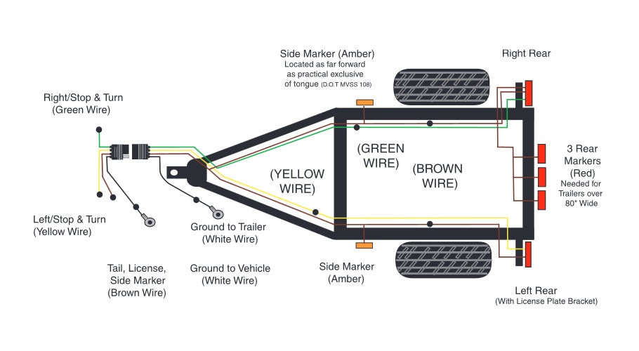
So, you're looking to understand trailer wiring diagrams. Smart move! Whether you're troubleshooting a faulty brake light, wiring up a new trailer, or just curious about how it all works, understanding the wiring diagram is crucial. This article will break down the ins and outs of trailer electrical plug wiring diagrams, giving you the knowledge to confidently tackle trailer electrical projects.
Purpose: Why This Diagram Matters
A trailer wiring diagram is essentially a roadmap for the electrical system connecting your tow vehicle to your trailer. It visually represents how each wire in the trailer plug corresponds to specific functions on the trailer, such as lights, brakes, and auxiliary power. Without a diagram, you're left guessing, which can lead to short circuits, damage to your vehicle's electrical system, and, most importantly, safety hazards on the road.
Here’s why having a good understanding of trailer wiring diagrams is essential:
- Repair and Maintenance: Diagnosing and fixing electrical issues becomes significantly easier when you know which wire controls which function.
- New Trailer Wiring: If you’re wiring a trailer from scratch, the diagram guides you through the entire process.
- Custom Modifications: Adding auxiliary lights, batteries, or other electrical components requires a solid understanding of the existing wiring system.
- Preventing Damage: Incorrect wiring can damage both your tow vehicle's and trailer's electrical systems.
- Safety: Properly functioning lights and brakes are crucial for safe towing.
Key Specs and Main Parts
The most common type of trailer plug is the 7-way blade connector, also known as the RV blade connector. However, 4-way flat connectors are frequently found on smaller trailers. Let's look at the specs for each:
4-Way Flat Connector
The 4-way flat connector is a basic plug used primarily for lights. It typically carries the following functions:
- Ground (White): Provides a common ground for all circuits.
- Tail Lights (Brown): Powers the taillights.
- Left Turn Signal and Brake Light (Yellow): Combines the left turn signal and brake light function.
- Right Turn Signal and Brake Light (Green): Combines the right turn signal and brake light function.
7-Way Blade Connector (RV Blade)
The 7-way blade connector is more complex and provides a wider range of functions, including:
- Ground (White): Provides a common ground.
- Tail Lights (Brown): Powers the taillights.
- Left Turn Signal and Brake Light (Yellow): Combines the left turn signal and brake light function.
- Right Turn Signal and Brake Light (Green): Combines the right turn signal and brake light function.
- Electric Brakes (Blue): Powers the electric brakes on the trailer (requires a brake controller in the tow vehicle).
- Reverse Lights (Black): Activates the trailer's reverse lights when the tow vehicle is in reverse.
- Auxiliary Power (Red or Orange): Provides a 12V power source for charging batteries or powering accessories on the trailer.
Important Note: While these are the standard colors and functions, always verify the wiring diagram for your specific trailer, as manufacturers may occasionally deviate from these norms.
Symbols: Understanding the Wiring Diagram
A trailer wiring diagram uses symbols to represent different components and connections. Here's a breakdown of common symbols:
- Lines: Represent wires. Thicker lines often indicate wires carrying higher current.
- Dots: Indicate a connection between two or more wires.
- Rectangles: Represent components like lights, brake controllers, and batteries.
- Circles: Can represent various components, depending on the diagram's legend. Often used for fuses.
- Color Codes: Wires are typically labeled with color codes (e.g., WH for white, BR for brown, YL for yellow).
- Connectors: Represented by various shapes, showing how plugs are connected to the wiring.
Pay close attention to the legend or key provided with the diagram. This legend will explain the specific symbols used in that particular diagram.
How It Works
The basic principle is simple: the tow vehicle's electrical system provides power to the trailer's electrical components through the trailer plug. When you activate a function in the tow vehicle (e.g., turn signal, brake pedal), the corresponding signal is sent through the appropriate wire in the trailer plug to the trailer. The trailer's wiring then distributes this power to the correct lights, brakes, or other accessories.
For example, when you press the brake pedal in the tow vehicle, the brake light signal is sent through the yellow (left) and green (right) wires in a 4-way connector, or through dedicated wires in a 7-way connector. This signal activates the brake lights on the trailer, alerting drivers behind you.
For trailers with electric brakes, the tow vehicle needs a brake controller. The brake controller senses when you're braking and sends a variable voltage signal to the trailer's electric brakes through the blue wire in the 7-way connector. The higher the voltage, the stronger the braking force applied to the trailer.
Real-World Use: Basic Troubleshooting Tips
Here are some common problems and troubleshooting tips:
- No Lights: Check the ground connection first. A bad ground is a frequent culprit. Ensure the white wire is securely connected to both the tow vehicle and the trailer frame. Also, check the fuses in your tow vehicle that control trailer lights.
- One Light Not Working: Check the bulb first. If the bulb is good, inspect the wiring to that specific light for damage or loose connections. Use a multimeter to check for voltage at the light socket when the function is activated.
- Brakes Not Working: Verify the brake controller is properly installed and functioning. Check the blue wire for continuity between the tow vehicle and the trailer. Inspect the brake magnets on the trailer axles for damage.
- Short Circuits: Short circuits can blow fuses. Look for frayed wires or damaged insulation that could be causing a wire to ground out. Use a multimeter to check for continuity between the wires and the trailer frame.
- Flickering Lights: Often caused by loose connections or corroded terminals. Clean and tighten all connections in the wiring system.
Remember: Always disconnect the trailer plug from the tow vehicle before troubleshooting electrical problems to avoid accidental shorts or damage.
Safety: Highlight Risky Components
Working with electricity involves inherent risks. Here are some safety precautions to keep in mind:
- Disconnect Power: Always disconnect the trailer plug from the tow vehicle before working on the electrical system.
- Use a Multimeter: A multimeter is essential for diagnosing electrical problems. Learn how to use it safely and effectively.
- Protect Your Eyes: Wear safety glasses when working with wiring.
- Work in a Dry Area: Avoid working on electrical systems in wet or damp conditions.
- Proper Tools: Use insulated tools designed for electrical work.
- Fuses: Never replace a fuse with a higher amperage fuse. This can overload the circuit and cause a fire.
The most risky components are those carrying higher amperage, such as the auxiliary power wire and the electric brake wire. Handle these wires with extra caution and ensure they are properly insulated and protected.
Understanding your trailer's electrical system through the wiring diagram not only makes repairs easier but also ensures your safety and the safety of others on the road. With the knowledge presented here, you're well-equipped to tackle most common trailer wiring tasks.
We have a downloadable trailer wiring diagram file available for your reference. Use it wisely!