
Trailer Light Connector Wiring Diagram
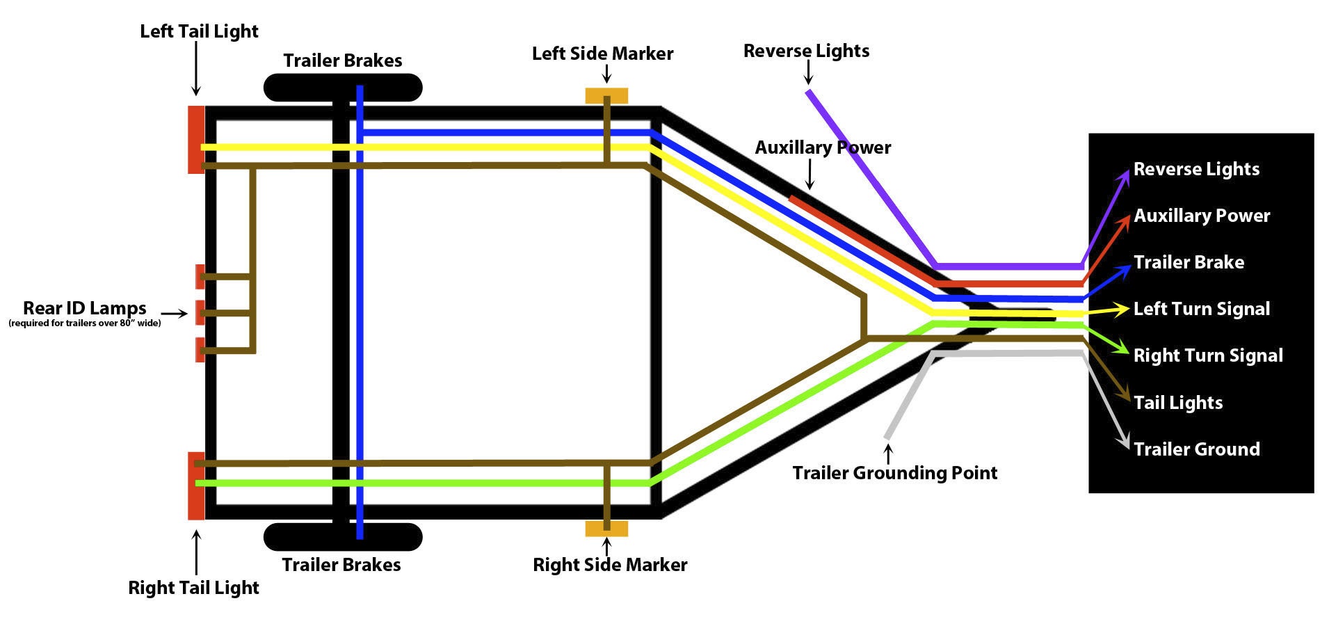
So, you're looking to understand trailer light connector wiring? Great choice! Knowing how these systems work is invaluable, whether you're tackling a repair, building a custom trailer setup, or just want to understand your vehicle better. This article breaks down the trailer light connector wiring diagram, providing the knowledge you need to confidently handle these connections.
Purpose and Why It Matters
A trailer light connector wiring diagram is essentially a roadmap for the electrical connections between your tow vehicle and your trailer. Its primary purpose is to ensure that all the trailer's lights – brake lights, turn signals, running lights (also known as tail lights), and sometimes reverse lights – function correctly and in sync with the tow vehicle. Understanding the diagram is crucial for several reasons:
- Repairing Faulty Connections: When trailer lights malfunction (e.g., one light isn't working, all lights are dim, or the brake lights are out), the diagram helps you trace the wiring and pinpoint the source of the problem.
- Custom Trailer Wiring: If you're building a trailer from scratch or customizing an existing one, the diagram is essential for establishing the correct wiring layout.
- Diagnosing Electrical Issues: Sometimes, problems in your tow vehicle's wiring can manifest as trailer light issues. The diagram helps you isolate whether the issue originates in the vehicle or the trailer.
- Preventing Electrical Fires: Improper wiring can lead to short circuits, which can generate excessive heat and potentially cause a fire. The diagram helps ensure correct and safe connections.
Key Specs and Main Parts
While variations exist, the most common trailer light connectors are the 4-way flat connector and the 7-way blade connector (also known as a Bargman connector). Here's a brief overview:
- 4-Way Flat Connector: This is the most basic type, commonly used for small trailers. It provides connections for:
- Ground
- Tail Lights (Running Lights)
- Left Turn/Brake Light
- Right Turn/Brake Light
- 7-Way Blade Connector: More versatile than the 4-way, the 7-way connector adds connections for:
- Ground
- Tail Lights (Running Lights)
- Left Turn Signal
- Right Turn Signal
- Brakes (Electric Brakes)
- Auxiliary Power (12V+) – Used for charging a trailer battery or powering interior lights.
- Reverse Lights
Key Specifications:
- Voltage: Typically 12V DC.
- Wire Gauge: The thickness of the wires. Generally, thicker wires are used for circuits with higher current draw (e.g., electric brakes). Using too thin a wire can lead to voltage drop and overheating. Refer to your trailer's documentation or a wiring chart for appropriate wire gauge based on the current load.
- Connector Type: As mentioned above, 4-way flat or 7-way blade are most common. Other types exist, such as 5-way flat (adding reverse lights to the 4-way) and various round connectors.
Symbols: Lines, Colors, and Icons
Understanding the symbols used in a trailer light connector wiring diagram is critical for accurate interpretation.
- Lines: Lines represent wires. Solid lines indicate a direct connection, while dashed lines might indicate a connection passing through a switch or relay.
- Colors: Wire colors are often standardized to aid in identification. Common colors include:
- White: Ground
- Brown: Tail Lights (Running Lights)
- Yellow: Left Turn/Brake Light (or Left Turn Signal)
- Green: Right Turn/Brake Light (or Right Turn Signal)
- Blue: Electric Brakes
- Black: Auxiliary Power (12V+)
- Purple: Reverse Lights
- Icons: Common icons represent:
- Light Bulbs: Represent the trailer lights (tail lights, brake lights, turn signals, reverse lights).
- Ground Symbol: A stylized symbol representing the connection to the vehicle's chassis or frame, providing a return path for the electrical current.
- Battery Symbol: Represents the auxiliary battery on the trailer (if equipped).
- Fuse Symbol: Indicates a fuse in the circuit, providing overcurrent protection.
- Relay Symbol: Represents a relay, an electrically operated switch used to control a high-current circuit with a low-current signal.
How It Works
The basic principle is simple: When you activate a light function in your tow vehicle (e.g., turn signal, brake lights), a corresponding signal is sent through the trailer light connector to the trailer. Here's a breakdown:
- Signal Initiation: When you activate a light (e.g., pressing the brake pedal), the vehicle's electrical system sends a signal to the corresponding wire in the trailer light connector.
- Signal Transmission: The signal travels through the appropriate wire in the connector and along the trailer's wiring harness.
- Light Activation: The signal reaches the light bulb, completing the circuit and causing the bulb to illuminate.
- Grounding: The electrical current returns to the vehicle's battery through the ground wire, completing the circuit. A good, clean ground connection is essential for proper operation.
For 7-way connectors with electric brakes, the vehicle's brake controller sends a variable voltage signal to the trailer's brake magnets, which then apply the trailer's brakes. The strength of the braking force is typically proportional to the amount of braking applied in the tow vehicle.
Real-World Use: Basic Troubleshooting Tips
Here are some common trailer light problems and how the wiring diagram can help:
- No Lights Working: Check the ground connection first! A poor ground is the most common culprit. Also, check the tow vehicle's trailer light fuses and the trailer's wiring for any obvious breaks or corrosion.
- One Light Not Working: Use the diagram to trace the wiring from the connector to the faulty light. Look for loose connections, damaged wires, or a burnt-out bulb.
- Dim Lights: Could indicate a poor ground, a corroded connection, or low voltage from the tow vehicle. Check the wiring diagram to identify the relevant circuits and inspect them thoroughly. Also, check the tow vehicle's charging system.
- Brake Lights Not Working: Check the brake light switch on the tow vehicle. Use a multimeter to verify that the brake light signal is reaching the trailer light connector. If not, the problem lies within the tow vehicle. If the signal is present at the connector, use the diagram to trace the wiring to the trailer's brake lights.
- Lights Work Intermittently: Usually caused by loose connections or damaged wiring. Flex the wiring harness and connectors to see if you can reproduce the problem. The wiring diagram will help you focus on the relevant circuits.
Safety: Highlight Risky Components
Working with electrical systems can be dangerous. Always disconnect the vehicle's battery before working on any wiring. Key safety points to remember:
- Battery Disconnect: Disconnecting the negative battery terminal is the first step.
- Proper Tools: Use insulated tools to prevent short circuits.
- Correct Wiring: Double-check your wiring against the diagram before making any connections. Incorrect wiring can damage your vehicle's electrical system or cause a fire.
- Fuse Protection: Ensure that all circuits are properly fused to prevent overcurrent situations.
- Heat Shrink Tubing: Use heat shrink tubing to insulate exposed wires and prevent corrosion.
The electric brake system, in particular, can be sensitive to overloads. Improper wiring or a malfunctioning brake controller can lead to overheating and potentially damage the brake magnets. Always consult the brake controller's manual and the trailer's wiring diagram for proper installation and troubleshooting.
With this knowledge and a wiring diagram, you're well on your way to confidently handling trailer light connector wiring. Remember safety first, double-check your connections, and don't hesitate to consult a professional if you're unsure about anything. We have prepared the file for the trailer light connector wiring diagram, you can download it at the link here.