
Trailer Wiring 4 Pin To 7 Pin Adapter
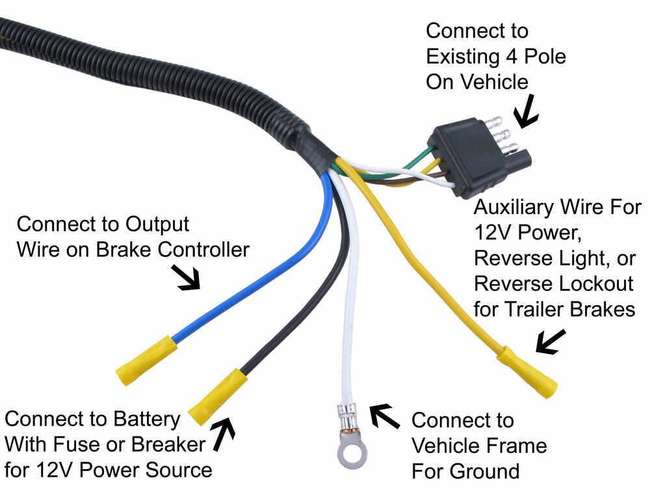
Alright, let's dive into the world of trailer wiring adapters, specifically the 4-pin to 7-pin conversion. If you're hauling anything bigger than a small utility trailer, chances are you'll encounter this sooner or later. This article provides a technical deep dive, perfect for experienced DIYers looking to understand, troubleshoot, or even build their own adapter solutions.
Purpose of a 4-Pin to 7-Pin Adapter
Why bother with this conversion? The fundamental reason is functionality. A standard 4-pin connector, also known as a flat-4, provides the bare essentials: ground, tail lights, left turn/brake, and right turn/brake. This is sufficient for small, unbraked trailers. However, larger trailers demand more.
A 7-pin connector expands on this by adding crucial circuits. These typically include:
- Electric Brakes: Enables control of trailer brakes, vastly improving safety and stopping power. This is almost mandatory for trailers exceeding a certain weight (check your local regulations).
- 12V Auxiliary Power: Provides a constant 12-volt power supply to the trailer. This can charge a trailer battery, operate interior lights, or power other onboard devices.
- Reverse Lights: Activates the trailer's reverse lights when the tow vehicle is in reverse, increasing visibility and safety during backing maneuvers.
Understanding this difference is critical for safe towing. Using a 4-pin connector on a trailer designed for a 7-pin connection will result in non-functional brakes, no auxiliary power, and potentially illegal operation.
Key Specs and Main Parts
Let's break down the components:
- 4-Pin Connector (Flat-4): The input side of the adapter. Usually molded plastic with four flat pins.
- 7-Pin Connector (Round): The output side. A robust, round connector with seven pins arranged in a specific configuration.
- Wiring Harness: The internal wiring that connects the 4-pin input to the 7-pin output. Wire gauge is critical here. Use appropriate gauge wire (typically 16-14 AWG) to handle the current loads, especially for the brake and auxiliary power circuits.
- Adapter Housing: Protects the wiring and provides a secure mounting point.
- Fuse(s) (Optional but Recommended): In-line fuses on the 12V auxiliary power and brake circuits provide protection against overloads and short circuits. These are vital for safety.
- Resistors (Rare): In some instances, particularly with newer vehicles that use CAN bus systems for lighting control, resistors might be needed to simulate the load of the trailer lights. Without them, the vehicle might detect an "open circuit" and trigger warning lights.
Understanding the Wiring Diagram Symbols
A wiring diagram is the roadmap of the adapter. Here's a quick glossary of common symbols:
- Solid Lines: Represent wires. The thickness of the line *might* indicate wire gauge in some diagrams.
- Dashed Lines: Often represent the adapter housing or indicate wires running behind components.
- Circles or Dots: Indicate connection points (splices or terminals).
- Color Codes: Wire colors are crucial for identification. Standard colors are generally used, but always verify with a reliable source. Common colors are: Yellow (Left Turn/Brake), Green (Right Turn/Brake), Brown (Tail Lights), White (Ground), Blue (Electric Brakes), Black (12V Auxiliary Power), Purple (Reverse Lights).
- Icons: Represent components such as fuses, resistors, and connectors. Standard electrical symbols apply.
You'll often see abbreviations like "LT" (Left Turn), "RT" (Right Turn), "TL" (Tail Lights), "GND" (Ground), "AUX" (Auxiliary), and "BK" (Brake). Familiarize yourself with these to quickly interpret the diagram.
How It Works: The Electrical Flow
The adapter's primary function is to remap the signals from the 4-pin connector to the appropriate pins on the 7-pin connector. Here's a simplified explanation of the signal routing:
- Ground (White): This is a common ground connection, shared by all circuits. It's crucial for completing the electrical circuit.
- Tail Lights (Brown): The tail light signal is passed directly to the corresponding pin on the 7-pin connector.
- Left Turn/Brake (Yellow): This signal is also passed directly through. When the left turn signal is activated, this wire carries the signal. When the brakes are applied, this wire carries the brake light signal.
- Right Turn/Brake (Green): Similar to the left side, this signal is passed directly through.
The *magic* happens with the added circuits:
- Electric Brakes (Blue): This wire *needs* to be connected to the brake controller output on your tow vehicle. This is NOT sourced from the 4-pin connector. The adapter usually has a separate wire that you must connect to the brake controller output wire in your vehicle. Incorrect connection can damage the brake controller or cause braking issues.
- 12V Auxiliary Power (Black): This also *needs* a separate connection to a 12V power source in your tow vehicle. Ideally, this should be directly connected to the battery, with an in-line fuse close to the battery. This provides a constant power supply to the trailer.
- Reverse Lights (Purple): This wire also requires a separate connection to the reverse light circuit of your tow vehicle. It's activated only when the vehicle is in reverse.
Real-World Use and Basic Troubleshooting
Let's say your trailer lights aren't working correctly. Here's a basic troubleshooting approach:
- Start with the Basics: Check the tow vehicle's lights. Are the turn signals, brake lights, and tail lights working correctly on the vehicle itself? If not, fix that first.
- Inspect the Connectors: Check both the 4-pin and 7-pin connectors for corrosion, bent pins, or loose connections. Clean and repair as needed. Use dielectric grease to prevent corrosion.
- Check the Ground: A bad ground is the most common cause of trailer light problems. Ensure the ground wire is securely connected to a clean, rust-free metal surface on both the tow vehicle and the trailer.
- Test with a Multimeter: Use a multimeter to check for voltage at the pins on the 7-pin connector when the corresponding lights are activated (turn signals, brake lights, etc.). If there's no voltage, the problem is upstream (likely in the adapter or the tow vehicle wiring).
- Inspect the Adapter Wiring: Carefully examine the wiring inside the adapter housing for any loose connections, damaged wires, or corroded terminals. Re-crimp or replace connections as needed.
- Check Fuses: If the auxiliary power or brake circuits aren't working, check the in-line fuses. Replace blown fuses with the correct amperage rating.
Safety Considerations
Working with electrical systems carries inherent risks. Here's what to keep in mind:
- Disconnect the Battery: Whenever working on electrical wiring, disconnect the negative terminal of the vehicle's battery to prevent short circuits and electrical shocks.
- Use Proper Tools: Use properly insulated tools designed for electrical work.
- Fuse Protection: Always use fuses of the correct amperage rating to protect the electrical circuits. Over-fusing can lead to overheating and fires.
- Brake Controller Compatibility: Ensure that the brake controller is compatible with the trailer's braking system. Incorrect brake controller settings can result in inadequate braking or even locked-up brakes.
- High Current Circuits: The 12V auxiliary power and brake circuits carry significant current. Use appropriate gauge wire and secure connections to prevent overheating and voltage drop.
- Avoid Automotive Airbags: When connecting the brake controller and reverse lights circuits of the tow vehicle, be extremely careful to avoid any wiring connected to the vehicle's airbag system. Erroneous voltage signals can cause the airbag to deploy unexpectedly.
This article provides a solid foundation for understanding 4-pin to 7-pin trailer wiring adapters. Remember to consult a qualified electrician if you are unsure about any aspect of the wiring or electrical system.
We have a detailed wiring diagram available for download to help you visualize the connections. Feel free to reach out and we will provide the file.