
Trailer Wiring Kit With Electric Brakes
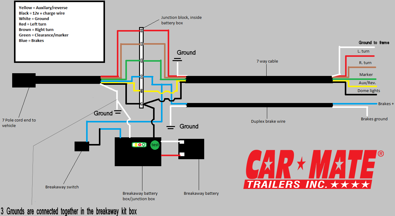
Let's talk about trailer wiring, specifically focusing on kits that incorporate electric brakes. Understanding this system is crucial for anyone towing heavier loads, not just for legal compliance in many jurisdictions, but more importantly, for the safety of yourself and others on the road. This article will break down the components, functionality, and troubleshooting aspects of trailer wiring kits designed for electric brakes. Whether you're diagnosing a problem, installing a new kit, or just trying to understand how it all works, this guide will provide the knowledge you need.
Purpose and Importance
Why bother with this diagram and explanation? Imagine your trailer, loaded with a boat or equipment, suddenly pushing your tow vehicle forward during braking – especially downhill or in wet conditions. That's a recipe for disaster. Electric brakes on trailers significantly improve stopping power and stability. This wiring diagram is essential for ensuring those brakes function correctly. It allows you to:
- Diagnose wiring issues: Trace faults, identify shorts, and repair broken connections.
- Install a new wiring kit: Follow a step-by-step guide to proper installation.
- Understand the system: Learn how the components interact and troubleshoot effectively.
- Ensure safe towing: Confirm that your electric brakes are operating as intended.
Key Specs and Main Parts
Trailer wiring kits for electric brakes aren't just about running a few wires; they involve specific components designed to handle the demands of braking. Here's a breakdown of the crucial elements:
7-Way RV Blade Connector
This is the industry standard connector for trailers with electric brakes. It's the interface between the tow vehicle and the trailer. The "blade" design refers to the flat, spade-like pins inside the connector.
Brake Controller
This is mounted in the tow vehicle and senses when you apply the brakes. It then sends an electrical signal to the trailer's electric brakes, proportional to the braking force of the tow vehicle. The brake controller is the "brains" of the operation, determining how much braking force is applied to the trailer. Gain is an important setting on the brake controller. It adjusts the sensitivity and power sent to the trailer brakes. Too little gain and the trailer won't brake effectively; too much and the trailer brakes will lock up.
Electric Brake Assemblies
Located on each wheel of the trailer, these assemblies contain electromagnets that, when energized, attract to a rotating drum or rotor. This friction slows the trailer wheels. The amount of electricity sent by the brake controller determines the strength of the magnetic force and, therefore, the braking force.
Wiring Harness
A collection of color-coded wires that connect all the components. These wires must be of sufficient gauge (thickness) to handle the electrical current required by the brake system. Using too thin of a wire can lead to voltage drop and reduced braking performance, or even overheating and fire.
Junction Box (Optional)
Some trailers use a junction box, often mounted on the trailer tongue, to simplify wiring connections and provide a central location for testing. It's essentially a distribution point for all the trailer's electrical circuits.
Key Specs to consider:
- Wire Gauge: Typically, 12-gauge or 10-gauge wire is used for the electric brake circuit. Heavier trailers may require even thicker wire.
- Brake Controller Compatibility: Ensure the brake controller is compatible with the number of axles and brake type on your trailer (electric, electric-over-hydraulic).
- Connector Type: Confirm the connector type on your tow vehicle and trailer match (7-way RV blade is most common).
Symbols and Diagram Interpretation
Understanding the symbols used in a trailer wiring diagram is crucial for accurate interpretation. While variations exist, here are some common symbols and their meanings:
- Solid Lines: Represent wires. The thickness of the line might indicate wire gauge.
- Dashed Lines: Can represent ground connections or, less commonly, auxiliary circuits.
- Circles or Squares with Letters: Indicate specific connection points or components. For example, "BK" might denote the brake wire, "LT" left turn, and "RT" right turn.
- Color Codes: Wires are typically color-coded. Common colors include:
- White: Ground
- Blue: Electric brakes
- Brown: Tail lights and running lights
- Yellow: Left turn and brake lights
- Green: Right turn and brake lights
- Red: Auxiliary power (e.g., charging a trailer battery)
- Black: 12V power (often for brake controller)
- Ground Symbol: Looks like an inverted pyramid or a series of horizontal lines getting progressively shorter. Indicates a connection to the vehicle's chassis, which serves as the ground path.
The diagram will show how these components are interconnected, illustrating the flow of electricity from the tow vehicle, through the brake controller, to the electric brake assemblies on the trailer.
How It Works
The magic of electric trailer brakes lies in the interaction between the brake controller and the electric brake assemblies. Here's the sequence of events:
- Braking Initiation: When the driver applies the brakes in the tow vehicle, the brake controller senses this action. Some brake controllers use a pendulum or accelerometer to measure deceleration, while others rely on the brake light signal.
- Signal Transmission: The brake controller sends a variable voltage signal (typically 0-12V DC) to the blue wire (electric brake wire) of the 7-way connector. The voltage is proportional to the braking force desired.
- Electromagnet Activation: The blue wire carries the voltage to the electric brake assemblies on the trailer. Inside each assembly, the voltage energizes an electromagnet.
- Friction Engagement: The energized electromagnet attracts to the rotating brake drum or rotor. This attraction forces a lever arm to press the brake shoes against the drum or rotor, creating friction and slowing the wheel.
- Braking Force Control: The amount of braking force applied is directly proportional to the voltage sent by the brake controller. Higher voltage means a stronger magnetic field, more friction, and more braking power.
The ground wire (white) completes the circuit, allowing the electricity to return to the tow vehicle's electrical system.
Real-World Use: Basic Troubleshooting
Here are a few common issues and troubleshooting tips:
- No Trailer Brakes: Check the brake controller settings (gain). Verify the blue wire connection between the tow vehicle and trailer. Inspect the electric brake assemblies for damage or corrosion. Use a multimeter to test for voltage at the brake assemblies when the brake pedal is pressed.
- Weak Trailer Brakes: Could be low gain setting on the brake controller, corroded wiring connections, or worn brake shoes. Check the brake magnets for proper operation and adjust the brake shoes if necessary.
- Trailer Brakes Lock Up: Reduce the gain setting on the brake controller. Inspect the brake assemblies for binding or sticking components. A malfunctioning brake controller can also cause this.
- Blown Fuses: Indicates a short circuit. Carefully inspect the wiring harness for damaged insulation or pinched wires. A common culprit is the blue brake wire shorting to ground.
Tools you'll need: Multimeter, wire stripper/crimper, circuit tester, electrical tape, and potentially a brake adjustment tool.
Safety Considerations
Working with electrical systems always carries risk. Disconnect the tow vehicle's battery negative terminal before working on the wiring to prevent accidental shorts. Be especially careful when working near the 12V power wire (typically black) as it can deliver a significant shock. Ensure all wiring connections are secure and properly insulated to prevent corrosion and short circuits.
The brake controller itself can be a source of problems if not installed correctly. Follow the manufacturer's instructions carefully. Also, be aware that some older brake controllers may not be compatible with newer vehicle electrical systems, especially those with LED lighting or advanced driver-assistance systems (ADAS). Using an incompatible brake controller can damage the vehicle's computer or trigger error messages.
Finally, always test the trailer brakes in a safe, controlled environment before heading out on the road. Start with a low gain setting and gradually increase it until the trailer brakes are working effectively without locking up.
We have a detailed wiring diagram available for download to help you visualize the concepts discussed here. This diagram will serve as a valuable reference during installation, troubleshooting, and repair.