Transit Upfitter Switches Ford Transit Dual Battery Wiring Diagram
Understanding the Ford Transit's dual battery system and upfitter switches is crucial for anyone looking to add auxiliary equipment, perform maintenance, or simply diagnose electrical issues. This article will break down a typical Ford Transit dual battery wiring diagram and the upfitter switch setup, providing you with the knowledge to confidently work on your van's electrical system. We'll aim for clarity, assuming you have some familiarity with automotive wiring but might not be an electrical engineer.
Purpose of Understanding the Diagram
Why bother learning about this? Here's a few compelling reasons:
- Adding Auxiliary Equipment: Installing lights, winches, inverters, or other accessories often requires tapping into the vehicle's electrical system. Understanding the diagram allows you to do this safely and efficiently.
- Troubleshooting Electrical Problems: When something goes wrong, a wiring diagram is your best friend. It helps you trace circuits, identify faulty components, and pinpoint the source of the problem.
- Repair and Maintenance: Replacing a battery, alternator, or other electrical component becomes much easier with a clear understanding of the wiring involved.
- Customization and Modification: If you're building out your Transit for camping or other purposes, you'll likely need to modify the electrical system. The diagram is essential for planning and executing these modifications.
- Avoiding Costly Mistakes: Working on an electrical system without proper knowledge can lead to shorts, blown fuses, and even damage to your vehicle. Understanding the diagram helps you avoid these mistakes.
Key Specs and Main Parts
Before diving into the diagram, let's define the key components and specifications typically found in a Ford Transit dual battery setup with upfitter switches:
- Starting Battery: This is the primary battery, used to start the engine. It's typically a high-CCA (Cold Cranking Amps) battery.
- Auxiliary Battery (House Battery): This battery powers auxiliary equipment when the engine is off. It's usually a deep-cycle battery designed for sustained discharge and recharge cycles.
- Battery Management System (BMS): This system monitors and controls the charging and discharging of both batteries, ensuring optimal performance and longevity. It may include components like a battery isolator or a DC-to-DC charger.
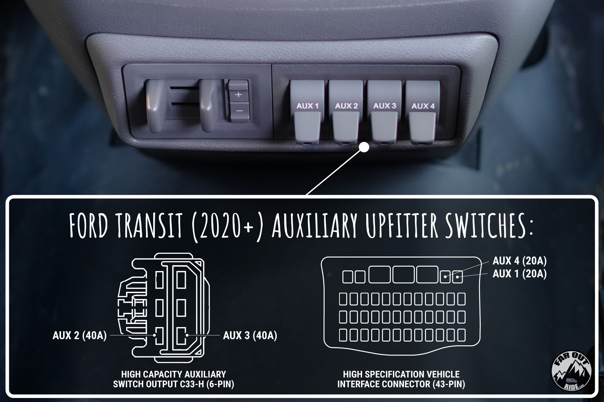
- Upfitter Switches: These are pre-wired switches in the cabin that allow you to easily connect and control auxiliary equipment. They are typically rated for a specific amperage.
- Fuses and Relays: These protect the electrical system from overloads and control the flow of current to various components.
- Grounding Points: These are connection points where wires are attached to the vehicle's chassis, providing a common ground for the electrical system.
- Wiring Harnesses: These are bundles of wires that connect different parts of the electrical system. They are often color-coded for easy identification.
Typical voltage for these systems is 12V DC. Amperage ratings will vary depending on the specific Transit model and options, so always consult your vehicle's documentation.
Understanding Symbols and Conventions
Wiring diagrams use a standardized set of symbols and conventions to represent electrical components and connections. Here are some common symbols you'll encounter:
- Solid Lines: Represent wires. Line thickness can sometimes indicate wire gauge (thicker lines usually mean thicker wires).
- Dashed Lines: May indicate shielded wires, or ground connections (depending on the specific diagram).
- Circles: Often represent connection points or terminals.
- Rectangles: Can represent various components, such as relays, switches, or modules. A rectangle with a diagonal line through it often represents a resistor.
- Zigzag Line: Represents a resistor.
- Ground Symbol: Usually looks like a series of descending horizontal lines connected vertically.
- Battery Symbol: A series of alternating long and short parallel lines.
- Fuse Symbol: A wavy line or a small rectangle with a jagged line inside.
- Relay Symbol: A coil symbol connected to a switch symbol.
- Color Codes: Wires are typically color-coded to aid in identification. For example, red is often used for positive (12V) wires, and black is often used for ground wires. Common color codes include BLU (blue), GRN (green), YEL (yellow), and WHT (white). Abbreviations like "BLU/WHT" indicate a blue wire with a white stripe.
Pay close attention to the legend or key provided with the diagram. This will explain the specific symbols and color codes used in that particular diagram.
How It Works: Dual Battery and Upfitter Switch Integration
Here's a simplified explanation of how the dual battery system and upfitter switches work together:
- Battery Charging: The alternator charges both the starting battery and the auxiliary battery. A BMS ensures that both batteries are charged efficiently and prevents overcharging. This may involve a battery isolator (a diode or relay that prevents the auxiliary battery from draining the starting battery when the engine is off) or a DC-to-DC charger (which provides a regulated charge to the auxiliary battery).
- Powering Auxiliary Equipment: The auxiliary battery powers auxiliary equipment when the engine is off. This prevents the starting battery from being drained, ensuring that you can always start the engine.
- Upfitter Switch Connection: The upfitter switches are pre-wired to a power distribution box, typically located under the driver's seat or in the engine compartment. Each switch is connected to a dedicated circuit with its own fuse.
- Connecting Equipment to Upfitter Switches: You can connect your auxiliary equipment to the upfitter switches by tapping into the appropriate wires in the power distribution box. Always consult the wiring diagram to identify the correct wires.
- Switch Activation: When you flip an upfitter switch, it completes the circuit, allowing power to flow from the auxiliary battery (or the starting battery, depending on the configuration) to your auxiliary equipment.
Crucially, the upfitter switches are typically wired to only function when the ignition is ON. This prevents accidental battery drain. However, some configurations allow you to modify this behavior.
Real-World Use: Basic Troubleshooting
Let's look at some basic troubleshooting scenarios:
- Upfitter Switch Not Working:
- Check the Fuse: This is the first thing to check. Locate the fuse associated with the upfitter switch and replace it if it's blown.
- Check the Switch: Use a multimeter to check for continuity across the switch terminals when the switch is in the "on" position. If there's no continuity, the switch is likely faulty.
- Check the Wiring: Inspect the wiring for any loose connections, damaged wires, or corrosion.
- Auxiliary Battery Not Charging:
- Check the BMS: Ensure the battery management system is functioning correctly. Check for error codes or warning lights.
- Check the Battery Isolator/DC-to-DC Charger: Test the voltage input and output of the isolator or charger. If it's not working properly, it may need to be replaced.
- Check the Wiring: Inspect the wiring between the alternator, batteries, and BMS for any loose connections, damaged wires, or corrosion.
- Excessive Battery Drain:
- Identify the Culprit: Disconnect auxiliary equipment one at a time to see if the drain stops.
- Check for Shorts: Use a multimeter to check for shorts in the wiring of auxiliary equipment.
- Battery Health: Have both batteries load tested.
Safety Precautions
Working with automotive electrical systems can be dangerous. Here are some important safety precautions:
- Disconnect the Battery: Before working on any electrical components, disconnect the negative terminal of both batteries. This will prevent accidental shorts and electrical shocks.
- Use Proper Tools: Use insulated tools designed for automotive electrical work.
- Wear Safety Glasses: Protect your eyes from sparks and debris.
- Consult the Wiring Diagram: Always refer to the wiring diagram to identify the correct wires and components.
- Double-Check Your Work: Before reconnecting the battery, double-check all connections to ensure they are secure and properly insulated.
- Be Aware of Capacitors: Some electronic components, such as capacitors, can store a charge even after the battery has been disconnected. Discharge capacitors before handling them.
- High-Current Components: Components like the alternator, starter motor, and battery cables carry high currents. Be extremely careful when working around these components. A short circuit in these areas can cause severe burns or even an explosion.
Remember: When in doubt, consult a qualified automotive electrician. It's better to be safe than sorry, especially when dealing with electricity.
We have access to a comprehensive Ford Transit Dual Battery Wiring Diagram and Upfitter Switch Diagram. To access this file, please contact us through [Insert Contact Method Here - E.g., website contact form, email address]. Provide your Transit model year and configuration for accurate results. We are here to help get you started.