Transmission Wiring Harness Replacement Cost
Let's talk about something that can be a real headache: replacing a transmission wiring harness. If you're a seasoned DIYer or a car enthusiast, understanding the process and associated costs can save you a lot of money and prevent further damage to your vehicle. This guide will break down the complexities of transmission wiring harness replacement, from understanding its purpose to troubleshooting common issues and highlighting crucial safety precautions.
Purpose and Importance
The transmission wiring harness is the central nervous system of your automatic transmission. It's a bundle of wires and connectors that relays signals between the transmission control module (TCM) – sometimes integrated into the engine control module (ECM) – and various sensors and actuators within the transmission. These components control essential functions like gear shifting, torque converter lockup, and fluid pressure. A faulty wiring harness can lead to a cascade of problems, including:
- Erratic or harsh shifting
- Transmission slipping
- Failure to shift at all
- Illumination of the check engine light (CEL) with transmission-related diagnostic trouble codes (DTCs)
- Reduced fuel economy
Understanding the wiring harness and its role allows you to diagnose transmission issues more accurately and potentially perform repairs yourself. This saves on labor costs and gives you a deeper understanding of your vehicle's operation.
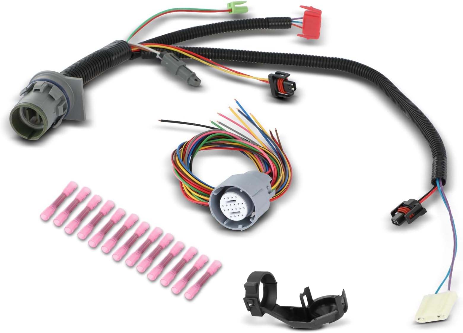
Key Specs and Main Parts
A transmission wiring harness isn't just a generic cable; it's a meticulously designed component with specific specifications. Here's a breakdown:
- Conductors: The wires themselves are typically made of copper, chosen for its excellent conductivity. The gauge (thickness) of the wire is crucial; different circuits require different current-carrying capacities. Higher gauge numbers (e.g., 20 AWG) indicate thinner wires, while lower numbers (e.g., 12 AWG) indicate thicker ones.
- Insulation: Each wire is insulated to prevent short circuits. Common insulation materials include PVC (Polyvinyl Chloride), XLPE (Cross-linked Polyethylene), and Teflon. The choice depends on the temperature and chemical resistance requirements of the application.
- Connectors: These are the interface points between the harness and the transmission components. They must provide a secure and weatherproof connection. Common connector types include Molex, Delphi, and AMP. They often have locking mechanisms to prevent accidental disconnection. Pins inside the connector are often crimped or soldered to the wire, and their integrity is crucial for reliable signal transmission.
- Sheathing: The entire bundle of wires is often protected by a sheathing, typically made of corrugated plastic or woven fabric. This protects the wires from abrasion, heat, and moisture.
- Grounding Straps: These are crucial for providing a good electrical ground, which is essential for the proper operation of many sensors. A poor ground can lead to false readings and erratic behavior.
When sourcing a replacement harness, make sure it matches the original equipment manufacturer (OEM) specifications for your vehicle's make, model, and year. Using an incorrect harness can cause serious damage.
Understanding Wiring Diagram Symbols
Working with a transmission wiring diagram requires familiarity with its symbols. Here's a basic overview:
- Lines: Solid lines represent wires. Dashed lines may indicate shielding or connections that are not part of the main circuit. The thickness of the line doesn't usually indicate wire gauge.
- Colors: Wire colors are represented by abbreviations (e.g., BLK for black, RED for red, GRN for green, YEL for yellow, BLU for blue, WHT for white). Some diagrams also use two-letter abbreviations (e.g., BK for black, RD for red). Color coding is crucial for identifying specific wires within the harness.
- Circles and Squares: These usually represent connectors or components. Numbers or letters inside the shape indicate pin numbers or component identifiers.
- Ground Symbols: Various symbols are used to represent ground connections. The most common is a series of horizontal lines decreasing in length.
- Relay Symbols: A relay is represented by a coil and a switch. The coil is usually depicted as a rectangle with a winding inside. The switch shows the contacts that are opened or closed when the relay is energized.
- Sensor Symbols: Specific symbols are used for different types of sensors, such as speed sensors, temperature sensors, and pressure sensors. These symbols usually include a representation of the sensing element.
Important note: Always consult the specific wiring diagram for your vehicle. Diagram conventions can vary between manufacturers.
How It Works
The TCM relies on input from various sensors to determine the optimal shift points and torque converter operation. These sensors include:
- Input Speed Sensor (ISS): Measures the speed of the transmission input shaft.
- Output Speed Sensor (OSS): Measures the speed of the transmission output shaft.
- Transmission Fluid Temperature (TFT) Sensor: Monitors the temperature of the transmission fluid.
- Throttle Position Sensor (TPS): Provides information about the throttle opening angle.
Based on this data, the TCM sends signals to various actuators, such as:
- Shift Solenoids: Control the flow of hydraulic fluid to engage different gears.
- Torque Converter Clutch (TCC) Solenoid: Controls the lockup of the torque converter, improving fuel economy.
- Pressure Control Solenoids: Regulate the hydraulic pressure within the transmission.
The wiring harness provides the pathways for these signals to travel. A break or short in the harness can disrupt this communication, leading to transmission malfunctions.
Real-World Use – Basic Troubleshooting Tips
Here are a few troubleshooting tips when dealing with a faulty transmission wiring harness:
- Visual Inspection: Carefully inspect the harness for any signs of damage, such as cracks, chafing, or melted insulation. Pay close attention to areas where the harness comes into contact with sharp edges or hot components.
- Connector Inspection: Check the connectors for corrosion, loose pins, or bent contacts. Use a connector cleaning spray to remove any corrosion.
- Continuity Testing: Use a multimeter to check the continuity of each wire in the harness. Disconnect both ends of the wire and measure the resistance. A high resistance indicates a break in the wire.
- Short-to-Ground Testing: Use a multimeter to check for shorts to ground. Disconnect the harness from the TCM and measure the resistance between each wire and a known good ground. A low resistance indicates a short to ground.
- Voltage Testing: Use a multimeter to check the voltage at various points in the harness. Refer to the wiring diagram to determine the expected voltage levels.
Example: Let's say your OBD-II scanner throws a P0741 code (Torque Converter Clutch Circuit Performance or Stuck Off). You'd want to check the wiring and connector for the TCC solenoid first. Use a multimeter to verify voltage is reaching the solenoid when commanded on by the TCM. If no voltage is present, trace the wiring back to the TCM, looking for breaks or shorts. If voltage *is* present, the solenoid itself is likely the problem.
Safety Precautions
Working with electrical systems can be dangerous. Here are some essential safety precautions:
- Disconnect the Battery: Always disconnect the negative battery cable before working on any electrical components. This will prevent accidental short circuits and electrical shocks.
- Use Proper Tools: Use insulated tools designed for electrical work.
- Avoid Water: Never work on electrical systems in wet conditions.
- Identify High-Voltage Components: Be aware of any high-voltage components in the engine compartment, such as the ignition system. These components can deliver a dangerous shock even with the battery disconnected.
- Consult a Professional: If you are not comfortable working with electrical systems, consult a qualified mechanic.
Replacement Cost
The cost of replacing a transmission wiring harness can vary depending on several factors, including:
- Vehicle Make and Model: Some vehicles have more complex wiring harnesses than others.
- Harness Location: Some harnesses are easier to access than others.
- OEM vs. Aftermarket: OEM harnesses are typically more expensive than aftermarket harnesses.
- Labor Costs: Labor costs can vary depending on the mechanic's hourly rate and the complexity of the job.
Generally, you can expect to pay between $200 and $800 for a transmission wiring harness replacement, including parts and labor. The harness itself can range from $50 to $300, while labor can range from $150 to $500, depending on the accessibility.
Pro Tip: Get quotes from multiple shops before committing to a repair. Ask for a detailed breakdown of the parts and labor costs.
Conclusion
Replacing a transmission wiring harness can be a challenging but rewarding task for experienced DIYers. By understanding the purpose of the harness, its components, and basic troubleshooting techniques, you can potentially save a significant amount of money. Remember to always prioritize safety and consult a professional if you are unsure about any aspect of the repair.
We have a detailed transmission wiring diagram file available for download to aid you in your repairs. You can download it [link to file download]. Good luck with your repair!