
Travel Trailer Battery Wiring Diagram
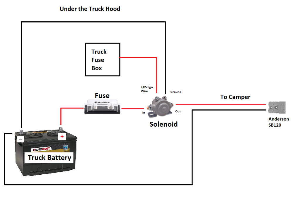
So, you're diving into the electrical guts of your travel trailer? Smart move! Understanding your travel trailer battery wiring diagram is crucial for everything from basic maintenance and troubleshooting to performing upgrades and even designing custom electrical systems. This guide will walk you through the key components, how it all works together, and some practical tips to keep you safe and your trailer powered up.
Purpose: Why This Diagram Matters
Think of your battery wiring diagram as the roadmap of your trailer's electrical system. Without it, you're navigating in the dark. It's essential for:
- Troubleshooting Electrical Issues: When lights flicker, appliances fail, or the battery won't charge, the diagram helps you pinpoint the source of the problem, whether it's a blown fuse, a loose connection, or a faulty component.
- Performing Repairs: Need to replace a wire, switch, or converter? The diagram shows you exactly where it connects and how to properly wire the replacement.
- Upgrading or Modifying the System: Adding solar panels, installing an inverter, or upgrading your battery bank? The diagram provides the foundation for planning and executing these modifications safely and effectively.
- Understanding System Operation: Even if you're not planning any immediate work, understanding the diagram helps you grasp how your trailer's electrical system is designed to function.
Key Specs and Main Parts
Before we dive into the diagram itself, let's review the key components you'll typically find in a travel trailer's 12V DC electrical system:
- Battery(ies): The heart of your 12V system, providing power when you're not connected to shore power. Common types include lead-acid (flooded, AGM, gel) and lithium-ion (LiFePO4). Battery capacity is measured in amp-hours (Ah).
- Battery Disconnect Switch: A switch that completely isolates the battery from the rest of the electrical system. This is important for storage and prevents parasitic draws from draining the battery.
- Fuses and Circuit Breakers: Overcurrent protection devices. Fuses are single-use devices that blow when the current exceeds their rating. Circuit breakers can be reset. They protect wiring and components from damage due to short circuits or overloads.
- Converter/Charger: Converts 120V AC shore power into 12V DC to power DC appliances and charge the battery. A multi-stage charger is preferable for optimal battery health.
- 12V Distribution Panel: A central point where 12V power is distributed to various circuits in the trailer. It typically houses fuses or circuit breakers for each circuit.
- Wiring: Various gauges of wire carry the electrical current. Wire gauge (AWG) is inversely proportional to the wire's current-carrying capacity. Thicker wire (lower AWG number) can handle more current.
- Grounding Bus Bar: A central point for all grounding wires in the system. Ensuring proper grounding is crucial for safety and preventing electrical noise.
- Appliances and Lights: Anything that runs on 12V DC power, such as lights, water pump, furnace fan, refrigerator controls, etc.
Symbols: Lines, Colors, and Icons
Understanding the symbols used in the wiring diagram is essential for interpreting it correctly. Here's a breakdown of common symbols:
- Solid Lines: Represent wires or conductors. The thickness of the line doesn't necessarily indicate wire gauge; that's usually specified separately.
- Dashed Lines: Often indicate wires running inside a conduit or bundle, or sometimes a connection point.
- Colors: Colors denote the function of the wire. Common colors include:
- Red: Positive (+) DC power.
- Black: Negative (-) DC power (ground).
- White: Neutral (AC systems, may sometimes be used for DC grounds as well - verify!).
- Green or Bare: Ground (AC and DC systems).
- Other colors (e.g., blue, yellow, brown): Used for specific circuits or functions. The diagram should include a color key.
- Icons: Graphical representations of components. Common icons include:
- Battery: Often depicted as a series of vertical lines or cells.
- Fuse: A zigzag line within a rectangle or circle.
- Circuit Breaker: Similar to a fuse, but with a manual reset lever.
- Switch: A line that can be opened or closed to control current flow.
- Resistor: A zigzag line.
- Ground: A series of descending horizontal lines, resembling an upside-down tree.
It is also helpful to note that some diagrams will include voltage and amperage ratings for various circuits and components. These are crucial for proper sizing of fuses and wiring.
How It Works
The basic principle is simple: the battery provides a source of 12V DC power. This power flows through the wiring, protected by fuses or circuit breakers, to various appliances and lights. When you're connected to shore power, the converter/charger steps in to provide 12V DC power and charge the battery.
Here's a simplified flow:
- Battery provides 12V DC power.
- Power flows through the battery disconnect switch (if enabled).
- Power reaches the 12V distribution panel.
- From the distribution panel, power is distributed to individual circuits, each protected by a fuse or circuit breaker.
- Each circuit powers specific appliances or lights.
- A complete circuit is formed when the power returns to the battery's negative terminal (ground).
When shore power is connected:
- 120V AC shore power enters the trailer.
- The converter/charger converts the 120V AC to 12V DC.
- The 12V DC power from the converter/charger powers the 12V appliances and charges the battery simultaneously.
Real-World Use: Basic Troubleshooting Tips
Here are a few common scenarios and how the wiring diagram can help:
- No Lights Working: Check the main fuse or circuit breaker for the 12V system. If it's blown, replace it with one of the same amperage rating. If it blows again immediately, there's a short circuit somewhere. Use the diagram to trace the wiring and identify potential problem areas.
- One Light or Appliance Not Working: Check the fuse or circuit breaker for that specific circuit. Consult the diagram to identify the correct fuse.
- Battery Not Charging: Check the converter/charger fuse or circuit breaker. Use a multimeter to verify that the converter/charger is outputting 12V DC power when connected to shore power. Also check the wiring between the converter/charger and the battery.
- Battery Draining Quickly: Turn off all lights and appliances and disconnect from shore power. Monitor the battery voltage. If it's dropping rapidly, there's likely a parasitic draw. Use the diagram to identify potential sources of parasitic draw (e.g., radio, propane detector, etc.) and disconnect them one by one to isolate the problem.
Safety: Highlight Risky Components
Working with electricity can be dangerous. Here are some safety precautions to take:
- Always disconnect from shore power and the battery before working on the electrical system. This eliminates the risk of electric shock.
- Use insulated tools.
- Never work on the electrical system in wet conditions.
- Double-check all connections before restoring power. Loose connections can cause fires.
- Use fuses and circuit breakers of the correct amperage rating. Using a higher-rated fuse can overload the wiring and cause a fire.
- Be especially careful when working with the battery. Batteries can produce explosive gases. Wear eye protection and avoid sparks or flames near the battery.
- Cap or insulate any wires that are disconnected.
- If you are uncomfortable working with electricity, consult a qualified electrician.
Remember to pay close attention to the polarity of the wires. Connecting the positive and negative wires incorrectly can damage components and create a fire hazard.
Understanding your travel trailer battery wiring diagram empowers you to maintain, troubleshoot, and upgrade your trailer's electrical system safely and effectively. By following these guidelines and taking the necessary precautions, you can keep your trailer powered up and ready for your next adventure.
For your convenience, we have a sample travel trailer battery wiring diagram available for download. This diagram can serve as a reference point and help you understand the general layout and components of a typical system. It is important to note that specific wiring configurations may vary depending on the make and model of your trailer. Therefore, you should always consult the wiring diagram specific to your trailer when performing any electrical work.
Download the diagram here: [Link to Download - Placeholder]