
Triton V8 Ford 5.4 Triton Engine Diagram
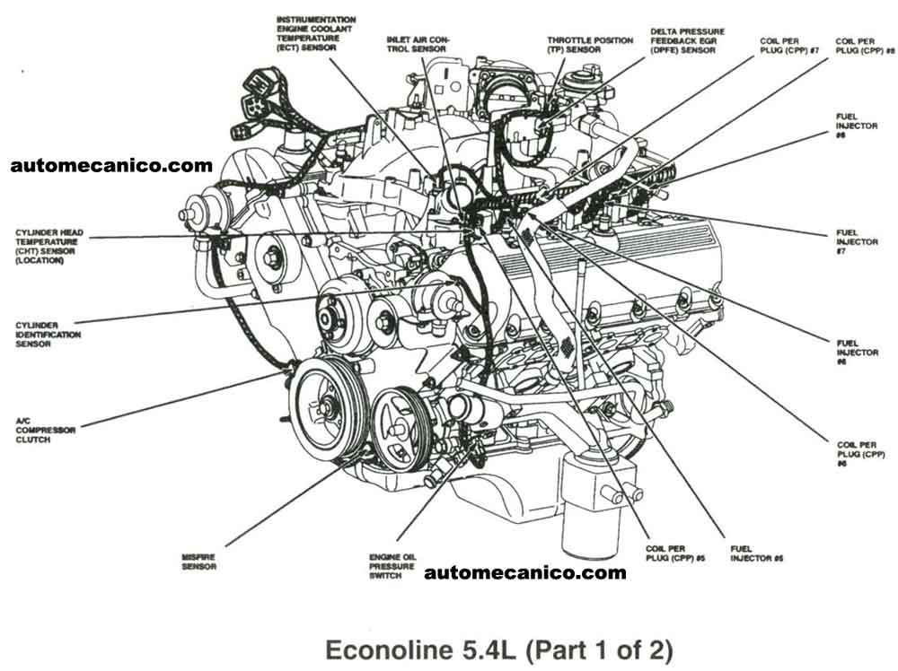
So, you’re diving into the Ford 5.4L Triton V8, huh? Smart move! Understanding this engine is key if you own a Ford truck or SUV from the late 90s to the late 2000s. This engine diagram isn't just a pretty picture; it's your roadmap for repairs, performance upgrades, and just plain understanding what's going on under your hood. We're going to break down everything from the major components to the symbols used in the diagram, giving you the knowledge to tackle common issues and keep your Triton running strong.
Purpose of the Diagram
Let's be clear: having a 5.4L Triton engine diagram is essential for any serious DIY mechanic. Why? It serves multiple crucial purposes:
- Troubleshooting: When your engine is acting up, the diagram helps you pinpoint the potential source of the problem. Is it a sensor issue? A vacuum leak? A faulty coil pack? The diagram guides your investigation.
- Repairing: Whether you're replacing a spark plug, intake manifold gasket, or even tackling a more complex job like timing chain replacement, the diagram shows you where everything is located and how it connects.
- Modifying/Upgrading: Planning on adding headers, a cold air intake, or a performance tuner? The diagram lets you visualize how these modifications will interact with the existing engine components.
- General Understanding: Even if you're not actively working on your engine, studying the diagram gives you a deeper understanding of how it all works. This can help you spot potential problems early and prevent costly repairs down the road.
Key Specs and Main Parts of the 5.4L Triton V8
Before we dissect the diagram itself, let's establish some basic facts about the 5.4L Triton V8:
- Displacement: 5.4 liters (330 cubic inches)
- Configuration: V8 (eight cylinders arranged in a V-shape)
- Valve Train: Generally, it's an SOHC (Single Overhead Camshaft) design, meaning each cylinder bank has one camshaft operating the valves. Some versions are 3-valve (2 intake, 1 exhaust) and others are 2-valve (1 intake, 1 exhaust). Knowing which version you have is critical for maintenance.
- Fuel Delivery: Sequential Multiport Fuel Injection (SMPI)
- Ignition: Coil-on-Plug (COP), meaning each spark plug has its own dedicated ignition coil.
Here are some of the main parts you'll find on the diagram, and their functions:
- Cylinder Block: The foundation of the engine, containing the cylinders and coolant passages.
- Cylinder Heads: Sit atop the cylinder block, housing the valves, camshaft(s), and combustion chambers.
- Pistons: Move up and down inside the cylinders, driven by the combustion process.
- Connecting Rods: Connect the pistons to the crankshaft.
- Crankshaft: Converts the linear motion of the pistons into rotational motion, which powers the vehicle.
- Intake Manifold: Distributes air to the cylinders.
- Exhaust Manifold: Collects exhaust gases from the cylinders.
- Fuel Injectors: Spray fuel into the intake ports or directly into the cylinders (depending on the specific engine design).
- Ignition Coils: Provide the high voltage needed to create a spark at the spark plugs.
- Spark Plugs: Ignite the air/fuel mixture in the cylinders.
- Water Pump: Circulates coolant through the engine to prevent overheating.
- Thermostat: Regulates the engine's operating temperature.
- Oil Pump: Circulates oil through the engine to lubricate moving parts.
- Sensors: Various sensors (e.g., crank position sensor, cam position sensor, mass airflow sensor, oxygen sensors) monitor engine parameters and provide data to the engine control unit (ECU).
Understanding Diagram Symbols
Engine diagrams use a variety of symbols to represent different components and connections. It's crucial to understand these symbols to properly interpret the diagram. Here are some common examples:
- Solid Lines: Typically represent fluid lines (e.g., coolant hoses, fuel lines, oil lines) or mechanical connections (e.g., linkages).
- Dashed Lines: Often indicate vacuum lines or electrical wiring. The specific pattern of dashes may differentiate different types of electrical circuits (e.g., power, ground, signal).
- Colors: Many diagrams use color-coding to distinguish between different fluids or electrical circuits. For example, blue might represent coolant, red might represent oil, and green might represent a specific type of electrical signal. The diagram will usually have a legend explaining the color codes.
- Circles and Squares: These often represent sensors, valves, or other components. The specific shape and any symbols inside the shape will indicate the type of component.
- Arrows: Indicate the direction of fluid flow or electrical current.
- Component Identifiers: Each component is typically labeled with a unique identifier (e.g., "MAF" for Mass Airflow Sensor, "CKP" for Crankshaft Position Sensor). The diagram's key or index will list these identifiers and their corresponding components.
Always refer to the diagram's legend or key to understand the specific symbols used in that particular diagram. Different diagrams may use slightly different conventions.
How the 5.4L Triton V8 Works (Simplified)
The 5.4L Triton V8 operates on the four-stroke combustion cycle:
- Intake: The intake valve opens, and the piston moves down, drawing a mixture of air and fuel into the cylinder.
- Compression: The intake valve closes, and the piston moves up, compressing the air/fuel mixture.
- Combustion: The spark plug ignites the compressed air/fuel mixture, creating a powerful explosion that forces the piston down.
- Exhaust: The exhaust valve opens, and the piston moves up, pushing the exhaust gases out of the cylinder and into the exhaust manifold.
The crankshaft converts the linear motion of the pistons into rotational motion, which is transmitted to the transmission and ultimately to the wheels. The engine's computer (ECU) controls the timing of the fuel injection and ignition to optimize performance and efficiency.
Real-World Use: Basic Troubleshooting
Let's say your 5.4L Triton is experiencing a rough idle. Here's how you might use the engine diagram to troubleshoot the problem:
- Check for Vacuum Leaks: Vacuum leaks can cause a rough idle. Use the diagram to identify all the vacuum lines connected to the intake manifold. Carefully inspect these lines for cracks, leaks, or loose connections. A common culprit is the PCV (Positive Crankcase Ventilation) valve and its associated hoses.
- Inspect Ignition System: A faulty ignition coil or spark plug can also cause a rough idle. The diagram will show you the location of each ignition coil and spark plug. You can use a multimeter to test the resistance of the ignition coils and a spark plug tester to check for spark.
- Examine Fuel Injectors: A clogged or faulty fuel injector can disrupt the air/fuel mixture. The diagram will show you the location of the fuel injectors. You can use a stethoscope to listen to each injector and check if it's clicking, indicating that it's firing. You can also perform a fuel injector cleaning service.
- Scan for Diagnostic Trouble Codes (DTCs): Use an OBD-II scanner to check for any stored trouble codes. These codes can provide valuable clues about the source of the problem. The engine diagram can help you understand the components related to the codes.
Safety Considerations
Working on your engine can be dangerous if you don't take proper precautions. Here are some safety tips:
- Disconnect the Battery: Before working on any electrical components, disconnect the negative battery cable to prevent shocks or shorts.
- Work in a Well-Ventilated Area: Engine fumes can be toxic. Work in a well-ventilated area to avoid inhaling harmful fumes.
- Wear Safety Glasses: Protect your eyes from flying debris or chemicals.
- Use Jack Stands: Never work under a vehicle supported only by a jack. Always use jack stands to support the vehicle securely.
- Be Careful with Fuel: Fuel is highly flammable. Avoid smoking or using open flames near fuel.
- Hot Surfaces: Be very careful when working around the exhaust manifold and other parts of the engine after its been running. These components get extremely hot and can cause burns.
- High Voltage: Be extremely careful when working around the ignition system. The ignition coils produce very high voltage that can be lethal. Always disconnect the battery and allow the system to discharge before touching any ignition components.
By using the diagram and following proper safety procedures, you can confidently tackle common issues and maintain the health of your 5.4L Triton V8.
Now, to further assist you in your repairs and modifications, we have a detailed 5.4L Triton engine diagram file available for download. It's a valuable resource to keep handy!