
Turn Signal Brake Light Wiring Diagram
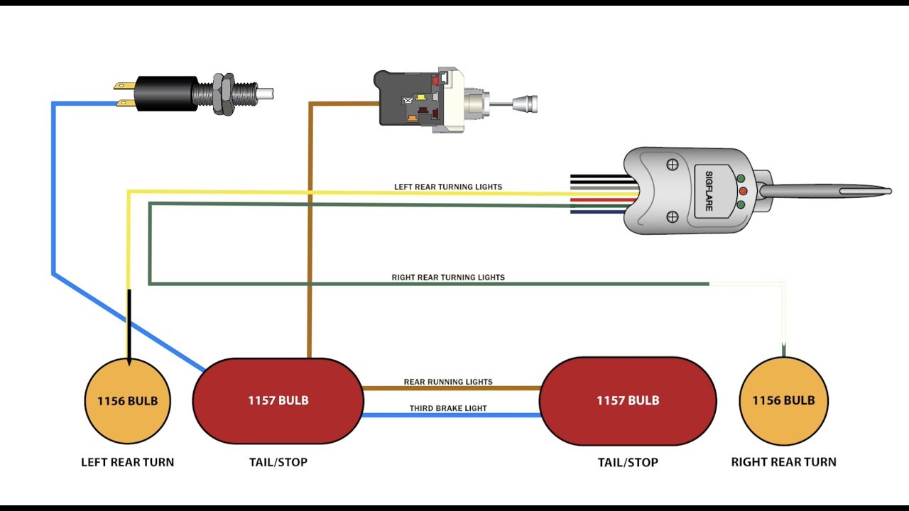
Alright, let's dive into the fascinating, and sometimes frustrating, world of turn signal and brake light wiring diagrams. If you're an experienced DIYer or a modder, understanding these diagrams is absolutely crucial. Whether you're tackling a simple bulb replacement, troubleshooting a persistent electrical gremlin, customizing your lighting setup, or even undertaking a full vehicle rewire, a clear understanding of the turn signal brake light wiring diagram is your best friend. It's your roadmap to avoiding electrical shorts, blown fuses, and, potentially, more serious damage. We’re going to break down everything you need to know to decipher these diagrams like a pro.
Purpose and Why You Need This
Think of a wiring diagram as the instruction manual for your car's electrical system, specifically focusing on the lights at the rear of your vehicle. Its primary purposes are:
- Repair and Diagnosis: Quickly pinpoint the source of a malfunctioning turn signal or brake light. Is it the bulb, a faulty switch, a broken wire, or something else? The diagram helps you narrow down the possibilities.
- Modification and Customization: Want to add aftermarket lights, upgrade to LEDs, or change the wiring for a custom lighting effect? The diagram shows you where to tap into the existing circuits and how to do it safely.
- Learning and Understanding: Gaining a deeper understanding of your vehicle's electrical system is empowering. Knowing how the turn signals and brake lights interact will make you a better mechanic and problem-solver.
- Preventative Maintenance: By understanding the system, you can identify potential weak points and address them before they cause bigger problems.
Key Specs and Main Parts
Before we jump into the diagram itself, let’s identify the key components typically found in a turn signal and brake light circuit:
- Battery: The heart of the electrical system, providing the power.
- Fuse: A safety device designed to protect the circuit from overloads. Always check the fuse first when troubleshooting!
- Ignition Switch: Controls the flow of power to various circuits when the car is turned on.
- Turn Signal Switch: Located on the steering column, it activates the left or right turn signals.
- Brake Light Switch: Usually located near the brake pedal, it activates the brake lights when the pedal is pressed.
- Flasher Relay (or Module): Causes the turn signal lights to blink on and off.
- Bulbs: The light source itself, which could be incandescent, halogen, or LED.
- Wiring: The conductive pathways that connect all the components.
- Ground (Chassis Ground): Provides a return path for the current, typically through the vehicle's metal frame.
- Connectors: Where wires join together, often points of corrosion and failure.
Understanding the Symbols
A wiring diagram uses a specific set of symbols and conventions to represent these components and their connections. Learning these symbols is key to interpreting the diagram.
- Lines: Solid lines represent wires. Thicker lines may indicate heavier gauge wires. Dashed lines can indicate wires that are shielded or part of a harness.
- Colors: Wires are color-coded to help identify them. The diagram will include a color key. Common colors include Red (power), Black (ground), Yellow (turn signal), Green (brake light). It is important to note that colors are vehicle specific and can change based on trim.
- Icons:
- Battery: A symbol resembling a battery, often with "+" and "-" signs.
- Fuse: A zig-zag line inside a rectangle.
- Switch: A break in a line with a pivoting arm.
- Bulb: A circle with a cross inside or a filament symbol.
- Ground: A series of downward-pointing lines, often resembling an upside-down Christmas tree.
- Relay: A coil symbol with a switch.
- Numbers and Letters: These often indicate wire gauge (e.g., 16 AWG) or connector pin numbers.
Important Note: Always refer to the specific wiring diagram for your vehicle. Generic diagrams can provide a general understanding, but the exact wiring configuration can vary significantly between makes, models, and even model years.
How It Works – Tracing the Circuit
Now, let's see how all this comes together. When you activate the turn signal switch, here’s a simplified overview:
- Power flows from the battery, through the ignition switch (if the car is on), and to the fuse protecting the turn signal circuit.
- From the fuse, the power reaches the flasher relay (or module). The flasher relay is responsible for interrupting the current flow at a regular interval, creating the blinking effect.
- When the turn signal switch is activated, it directs the pulsating power from the flasher relay to the appropriate turn signal bulbs (left or right).
- The current flows through the bulb filament, causing it to light up.
- The current then returns to the battery through the ground connection (usually the vehicle chassis).
The brake light circuit works similarly, but it's triggered by the brake light switch instead of the turn signal switch:
- Power flows from the battery, through the ignition switch, and to the fuse protecting the brake light circuit.
- When you press the brake pedal, the brake light switch closes, allowing current to flow to the brake light bulbs.
- The current flows through the bulb filament, causing it to light up.
- The current then returns to the battery through the ground connection.
In many modern vehicles, the turn signal and brake light circuits are integrated, meaning the same bulb is used for both functions. This is achieved through a more complex wiring arrangement that uses the brake light switch to override the turn signal signal when the brakes are applied.
Real-World Use – Basic Troubleshooting
Here are some common problems and how to troubleshoot them using the wiring diagram:
- No Turn Signals: Check the fuse first! Then, inspect the flasher relay. Use a multimeter to test for power at the turn signal switch. If power is present at the switch but not at the bulbs, check the wiring between the switch and the bulbs. Also, check the ground connection.
- One Turn Signal Works, the Other Doesn't: The most likely cause is a burnt-out bulb. However, it could also be a wiring problem or a faulty bulb socket on the side that isn’t working. Check the bulb socket for corrosion.
- Brake Lights Don't Work: Check the fuse and the brake light switch. Test the brake light switch with a multimeter to see if it’s sending power when the pedal is pressed.
- Turn Signals Work, But Blink Too Fast: This is often caused by a burnt-out bulb on one side, which reduces the load on the flasher relay. However, some vehicles require specific flasher relays for LED bulbs.
Remember to always disconnect the battery before working on any electrical components!
Safety – Risky Components
Working with automotive electrical systems can be dangerous. Here are some components to be particularly careful around:
- Battery: Contains corrosive acid and can produce explosive gases. Wear safety glasses and gloves when working near the battery.
- Fuses: Never replace a blown fuse with one of a higher amperage. This can overload the circuit and cause a fire.
- Wiring: Damaged wiring can create short circuits, which can cause fires or damage to electrical components. Always inspect wiring for damage before working on it.
- Airbags: Although not directly related to lighting, be aware of airbag locations when working under the dashboard or steering column. Accidental activation can cause serious injury. Consult your vehicle's service manual for proper airbag deactivation procedures.
Important Note: If you are not comfortable working with electrical systems, it's always best to consult a qualified mechanic. Improper wiring can damage your vehicle and even create a fire hazard.
With a good understanding of the wiring diagram and some basic troubleshooting skills, you can tackle many turn signal and brake light problems yourself. It's a rewarding and money-saving skill to develop. Now that you have a better understanding, you are welcome to download the turn signal brake light wiring diagram file that we have made available to you. This can assist you further on your way to DIY expert level.