Turn Signal Flasher 3 Pin Flasher Relay Wiring Diagram
So, you're tackling a turn signal issue, or maybe you're diving into some custom lighting mods? Understanding the 3-pin flasher relay wiring diagram is crucial. It's a fundamental part of any automotive electrical system, and knowing its ins and outs can save you time, frustration, and potentially a hefty repair bill. This guide breaks down the diagram in a way that's both technically accurate and easy to grasp for the experienced DIYer.
Purpose of Understanding the Diagram
Why bother with a wiring diagram in the first place? Several reasons. First, for repairs. A malfunctioning turn signal is often traced back to the flasher relay. Using the diagram helps you pinpoint the source of the problem, whether it's a faulty relay, a wiring issue, or a problem with the lamps themselves. Second, for modifications. If you're upgrading your lighting system, adding LED turn signals, or installing custom lighting setups, you need to know how the flasher relay integrates into the circuit. The diagram is your roadmap. Finally, for learning. Understanding the basic principles of the turn signal circuit will broaden your overall automotive electrical knowledge.
Key Specs and Main Parts
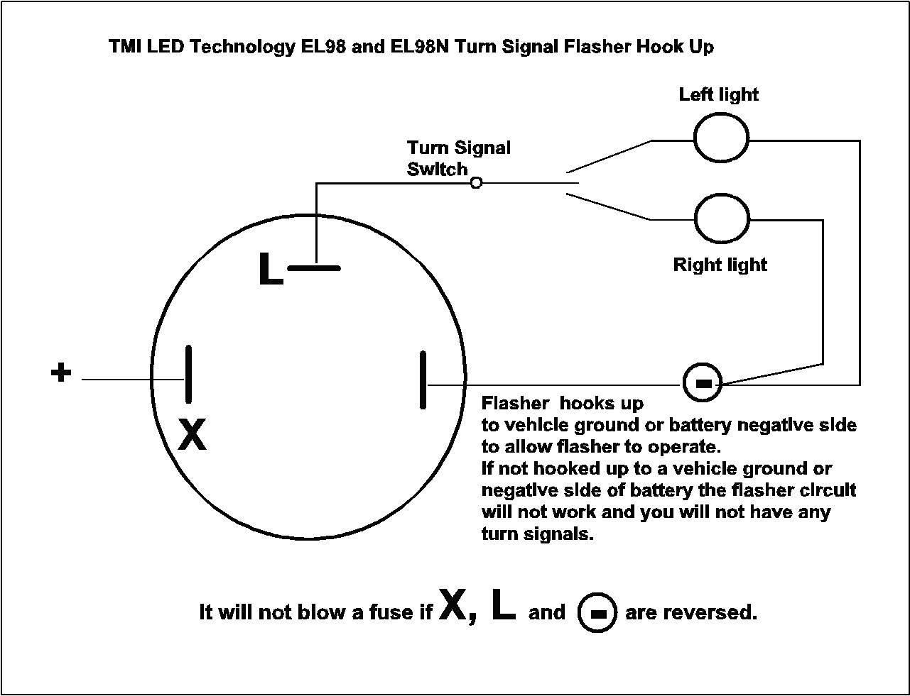
Let's identify the key components. The heart of the system is the 3-pin flasher relay. These relays are designed to interrupt the circuit, creating the flashing effect that we see in our turn signals. Here's a breakdown of the pins:
- Pin 30 (or B, or +): This is the power input, usually directly from the ignition switch or a dedicated fuse. It provides the voltage needed for the relay to operate.
- Pin 49 (or X, or L): This is the output to the turn signal switch. It carries the interrupted (flashing) power signal to the switch.
- Pin 31 (or E, or -): This is the ground connection. It completes the circuit, allowing the relay to function.
You'll also encounter other components in the overall turn signal circuit, although they're not directly part of the 3-pin flasher relay itself. These include:
- Turn Signal Switch: Directs the flashing signal to the left or right turn signal lamps.
- Turn Signal Lamps (Bulbs or LEDs): The actual lights that blink, indicating the direction of the turn.
- Fuses: Protect the circuit from overloads.
- Wiring: Connects all the components together.
Important specs to note include the voltage rating (typically 12V or 24V, depending on the vehicle) and the current rating (measured in amps). Using a relay with an insufficient current rating can lead to overheating and failure, especially if you're switching to LED lamps which often require relays designed for lower current draws.
Symbols Explained
Wiring diagrams use standardized symbols to represent components and connections. Here's a breakdown of what you'll typically find in a 3-pin flasher relay wiring diagram:
- Lines: Represent wires. Thicker lines may indicate wires with larger gauge (thicker wires carry more current).
- Colors: Wires are often color-coded to help identify them. Common colors include red (power), black (ground), and various colors for signal wires. The specific colors can vary between manufacturers and models, so always double-check your vehicle's specific wiring diagram.
- Relay Symbol: Typically a rectangle or square with the pin numbers (30, 49, 31 or B, L, E) clearly marked. Some diagrams may show the internal workings of the relay as a coil and a set of contacts.
- Ground Symbol: Usually a series of downward-pointing lines, indicating a connection to the vehicle's chassis ground.
- Lamp Symbol: A circle with an "X" inside, representing a light bulb. LED lamps might have a slightly different symbol.
- Fuse Symbol: A jagged line or a rectangle with a line through it, representing a fuse. The amperage rating of the fuse is usually indicated next to the symbol.
How It Works
The 3-pin flasher relay works on the principle of intermittent interruption. Here’s the process:
- Power Input: Voltage is supplied to Pin 30 (or B) when the ignition is on.
- Internal Mechanism: Inside the relay, a bimetallic strip (or an electronic circuit in more modern relays) heats up due to the current flow.
- Circuit Interruption: As the bimetallic strip heats up, it bends, causing the contacts to open and breaking the circuit. This stops the flow of current.
- Cooling and Reset: With the circuit broken, the bimetallic strip cools down, causing it to bend back to its original position and closing the contacts. This completes the circuit again.
- Repeating the Cycle: The process repeats continuously, creating the flashing effect. The rate of flashing is determined by the design of the relay and the resistance of the lamps. Using LED lights with too little resistance is a common reason for hyperflashing.
- Output to Switch: Pin 49 (or L) carries the interrupted power to the turn signal switch.
- Directional Control: The turn signal switch then directs the flashing power to the left or right turn signal lamps, depending on which direction the driver has selected.
- Ground Connection: Pin 31 (or E) provides the necessary ground for the internal circuit to function correctly.
Real-World Use: Basic Troubleshooting
Here's how you can use your understanding of the 3-pin flasher relay wiring diagram to troubleshoot common problems:
- No Turn Signals: First, check the fuse. If the fuse is blown, replace it. If the fuse blows again immediately, there's a short circuit somewhere in the system. Use the diagram to trace the wiring and look for damaged insulation or pinched wires. Next, test the flasher relay. You can use a multimeter to check for voltage at Pin 30 when the ignition is on. If there's voltage, but no flashing at Pin 49 when the turn signal is activated, the relay is likely faulty and needs to be replaced.
- Hyperflashing (Rapid Blinking): This usually indicates a problem with the load on the circuit. Most commonly, it's caused by a burnt-out bulb or the use of LED lamps without proper load resistors. Check all the bulbs and replace any that are burnt out. If you're using LEDs, you may need to install load resistors to simulate the resistance of a traditional incandescent bulb. The flasher relay itself may be designed specifically for LED bulbs.
- Turn Signals Stay On Continuously: This could indicate a stuck relay. The contacts inside the relay are not opening and closing properly. Replace the relay. Alternatively, there could be a short circuit in the wiring, causing the lamps to stay on continuously.
Safety Considerations
Working with automotive electrical systems involves some inherent risks. The battery is a source of significant current, so always disconnect the negative terminal before working on the electrical system. Be especially careful when working with fuses. Never replace a fuse with a higher amperage rating than specified. Doing so can overload the circuit and cause a fire. Wiring can also pose a risk. Always inspect wiring for damage, and use proper crimping and soldering techniques when making connections. Improper connections can lead to shorts and other electrical problems. Avoid contact with bare wires while the circuit is powered on.
Understanding the 3-pin flasher relay wiring diagram empowers you to diagnose and repair turn signal problems effectively. By knowing the components, the symbols, and the circuit's operation, you can confidently tackle these issues and save yourself time and money.
We have the file of the wiring diagram ready for you. You can download the comprehensive diagram to aid your troubleshooting and modification endeavors.