Two Lights One Switch Wiring Diagram
Alright, let's dive into a wiring diagram that's fundamental for anyone tinkering with automotive electricals: Two Lights, One Switch. It sounds simple, and it is, but understanding this basic setup is crucial for diagnosing lighting issues, adding auxiliary lights, or even just grasping the principles behind more complex circuits. We're going to break down the diagram, the components, and how it all works together, ensuring you can confidently apply this knowledge to your own projects.
Purpose of the Two Lights, One Switch Diagram
Why bother learning this? Several reasons: First, it's a building block. Many automotive circuits are based on this principle. Understanding how two lights are controlled by a single switch makes understanding more complex setups easier. Second, it's invaluable for troubleshooting. Got lights that aren't working right? Knowing this setup helps you isolate the problem, whether it's the switch, the wiring, or the lights themselves. Third, it's perfect for adding aftermarket lights. Thinking about adding some driving lights or auxiliary fog lights? This is the foundation for wiring them up correctly.
Key Specs and Main Parts
Before we get into the diagram, let's define the key components:
- Power Source: Typically, this will be your car's battery (12V DC system). Remember to always disconnect the negative terminal of the battery when working on electrical systems!
- Fuse: A critical safety device! A fuse protects the circuit from overcurrent. It contains a thin wire that melts and breaks the circuit if the current exceeds a specified value (e.g., 10 amps, 15 amps). Always use the correct amperage fuse for the circuit.
- Switch: The on/off control for the lights. A simple SPST (Single Pole, Single Throw) switch is typically used. This means it has one input terminal and one output terminal, and it either connects them or disconnects them.
- Wiring: The conductive pathways for the electricity. Automotive wiring is typically stranded copper wire, insulated with PVC or similar material. Wire gauge (thickness) matters! Use the correct gauge wire for the current draw of the lights to avoid overheating and potential fire hazards. Generally, thicker wires (lower gauge number) can handle more current.
- Lights: In this case, two light bulbs or LED assemblies. They are the "load" in the circuit, converting electrical energy into light.
- Ground (Earth): The return path for the electricity to the battery. In a car, the chassis (metal frame) is typically used as ground. Good, clean ground connections are essential for proper circuit operation.
Symbols in the Wiring Diagram
Understanding the symbols is key to reading the diagram:
- Straight Lines: Represent wires. A solid line indicates a conductive path.
- Dotted Lines (Sometimes): May indicate a wire hidden from view, or less crucial connections.
- Battery Symbol: A series of long and short parallel lines, indicating the positive and negative terminals.
- Fuse Symbol: A zigzag line enclosed in a rectangle.
- Switch Symbol: A break in the line with a pivoting arm to show the connection.
- Light Bulb Symbol: A circle with an "X" inside.
- Ground Symbol: Often looks like an inverted pyramid or a series of decreasing horizontal lines connected to a vertical line.
- Color Coding: Wiring diagrams often use colors to indicate the function of the wire (e.g., red for power, black for ground). However, always verify wire function with a multimeter, as color coding can vary between manufacturers.
How It Works: The Circuit in Action
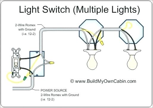
Here's how the two lights, one switch circuit works:
- Power from the battery flows through the fuse. The fuse protects the circuit from overcurrent.
- From the fuse, the power flows to one terminal of the switch.
- When the switch is closed (turned "on"), it completes the circuit, allowing power to flow to the next point.
- The power then splits (using a wire connector or splice) and travels to each of the two lights.
- Each light receives power, illuminates, and then the electricity exits the light.
- From each light, a wire connects to the ground (the car's chassis). This completes the circuit, allowing the electricity to flow back to the battery's negative terminal.
The key is that both lights are wired in parallel. This means that each light receives the full voltage (12V) and that if one light fails, the other will continue to work. If they were wired in series, if one light failed, both would go out.
Real-World Use: Troubleshooting Tips
Let's say your lights aren't working. Here's a basic troubleshooting approach using our understanding of the diagram:
- Check the Fuse: This is the first and easiest step. A blown fuse is a common cause of lighting problems. Use a multimeter to check for continuity across the fuse (continuity means the fuse is good).
- Check the Switch: Use a multimeter to check for continuity across the switch terminals when the switch is in the "on" position. If there's no continuity, the switch is likely faulty.
- Check the Lights: Test the lights individually by applying 12V directly to their terminals. If a light doesn't illuminate, it's bad.
- Check the Wiring: Look for damaged or corroded wires. Use a multimeter to check for continuity between the battery positive terminal (with the fuse in place and the switch on) and the light's positive terminal. Also, check for continuity between the light's negative terminal and ground. A lack of continuity indicates a broken wire or a bad connection.
- Check the Ground Connections: Make sure the ground connections are clean and secure. A poor ground connection can cause all sorts of electrical problems.
Safety: Highlighting Risky Components
Working with automotive electrical systems can be dangerous. Here are some critical safety points:
- Disconnect the Battery: Always disconnect the negative terminal of the battery before working on electrical systems. This prevents accidental shorts and potential damage to the vehicle's electrical system.
- Use Proper Tools: Use insulated tools designed for electrical work.
- Be Careful with Wiring: Avoid cutting or damaging wires. If you need to splice wires, use proper connectors and ensure the connections are secure.
- Don't Overload Circuits: Don't install lights that draw more current than the circuit is designed for. This can overload the wiring and cause a fire. Check the amperage rating of the fuse and the wire gauge to ensure they are adequate for the load.
- Work in a Well-Ventilated Area: Lead-acid batteries can release hydrogen gas, which is flammable.
The fuse is a critical safety component. Bypassing a fuse or using the incorrect amperage fuse can create a serious fire hazard.
By understanding the two lights, one switch wiring diagram, you're equipped to tackle a range of automotive electrical tasks. Take your time, double-check your work, and always prioritize safety.
We have a downloadable PDF of the diagram available for you. It includes a clean visual representation and detailed notes to help you with your projects. Feel free to request it, and we'll be happy to provide it!