
Two Lights Two Switches Wiring Diagram
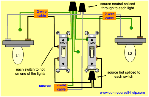
Welcome, fellow wrench-turners! Today, we're diving deep into a wiring setup that's more common than you might think – controlling two lights with two separate switches. This isn't just about flipping a light on or off; it's about understanding the flow of electricity and the logic behind simple control circuits. Whether you're troubleshooting existing wiring in your vehicle, customizing lighting setups, or simply expanding your electrical knowledge, this diagram and explanation will be invaluable. We're assuming you have a basic understanding of automotive electrical systems, but we'll break down the jargon as we go.
Purpose
Why bother learning about this specific wiring configuration? Several reasons stand out:
- Repairs: Identifying faults in existing circuits controlling auxiliary lights, interior lighting, or even components like heated seats often involves understanding the switch and wiring setup.
- Customization: Adding new lights – fog lights, driving lights, underglow – often requires integrating them into your vehicle's electrical system. Knowing how to wire them independently using separate switches offers flexibility and control.
- Learning: Understanding the basics of this two-switch, two-light system is a stepping stone to more complex automotive electrical circuits. It reinforces fundamental concepts like series and parallel circuits, ground, and power distribution.
- Safety: Modifying electrical systems without proper knowledge can be dangerous. A clear understanding helps prevent short circuits, blown fuses, and potential electrical fires.
Key Specs and Main Parts
Before we get into the diagram, let's define the core components:
- Power Source (Battery): The heart of the system, providing the electrical energy. Always work safely with the battery, disconnecting the negative terminal when working on electrical components.
- Fuse: A critical safety device. It's a sacrificial link that breaks the circuit if the current exceeds a safe level, preventing damage to components and wiring. Choose the appropriate amperage fuse for your lights.
- Switches (SPST - Single Pole Single Throw): These are the control points. In this scenario, we're using two SPST switches. An SPST switch simply opens or closes the circuit, allowing or blocking current flow.
- Lights (Load): The devices we're controlling – in this case, two separate lights. These could be anything from LED light bars to incandescent bulbs.
- Wiring: The copper conductors that carry the electrical current. Use appropriate gauge wire for the amperage draw of the lights. Thicker wire is better than thinner.
- Ground (Chassis Ground): The return path for the electrical current, typically the vehicle's metal frame. Ensuring a good ground connection is vital for proper circuit function.
Symbols Explained
Wiring diagrams use standardized symbols to represent components. Let's decode the most common ones you'll see in our diagram:
- Solid Line: Represents a wire. The longer the line, the longer the wire run in the actual vehicle.
- Dashed Line: Sometimes used to indicate a wire that's part of a harness or bundle, but not directly connected to the components we're focusing on.
- Circle with a "+" inside: Represents the positive (+) terminal of the power source (battery).
- Three Horizontal Lines (often descending): Represents ground (chassis ground). This is the return path for the current.
- Squiggly Line inside a Circle: Represents a light bulb (or any similar load, like an LED).
- Horizontal Line with a Break and a Toggle: Represents an SPST switch. The toggle indicates the switch position (open or closed).
- Fuse Symbol (rectangle with a squiggly line inside): Represents a fuse.
Wire Colors: Wire colors are often indicated in the diagram using abbreviations (e.g., Red = R, Black = BK, Blue = BL). These are guidelines, but always verify wire colors with a multimeter before making connections, especially in older vehicles.
How It Works
The basic principle is simple: each switch controls a separate light. Let's break down the current flow:
- Power flows from the battery's positive (+) terminal.
- It then passes through a fuse, protecting the circuit from overcurrent.
- The fused power wire splits into two separate paths, one for each switch.
- Each switch is connected to one of the lights.
- When a switch is closed (turned "on"), it completes the circuit, allowing current to flow through the light.
- After passing through the light, the current flows to ground (chassis ground), completing the circuit and illuminating the light.
- Opening the switch breaks the circuit, stopping the current flow and turning the light off.
Essentially, you have two independent circuits, each controlled by its own switch. The lights are wired in parallel, meaning each light receives the full voltage from the battery when its respective switch is closed.
Real-World Use – Basic Troubleshooting
Here are a few common problems and how to troubleshoot them using the diagram:
- One light doesn't work:
- Check the bulb. Is it blown?
- Check the fuse. Is it blown? If so, replace it with a fuse of the same amperage. If it blows again immediately, you have a short circuit.
- Check the switch. Use a multimeter to test for continuity across the switch terminals when it's in the "on" position. If there's no continuity, the switch is faulty.
- Check the wiring. Look for any broken, frayed, or disconnected wires. Use a multimeter to test for voltage at the light socket when the switch is "on". If there's no voltage, there's a break in the wire somewhere between the fuse and the light.
- Check the ground connection. Make sure the light is properly grounded to the chassis. A loose or corroded ground connection can prevent the light from working.
- Both lights don't work:
- Check the fuse. This is the most likely culprit.
- Check the battery voltage. Is the battery fully charged?
- Fuse keeps blowing:
- This indicates a short circuit. Carefully inspect the wiring for any places where the positive wire might be touching ground (the vehicle's chassis).
- A faulty light or switch can also cause a short circuit.
Safety
Electrical work can be dangerous. Here are some crucial safety precautions:
- Disconnect the Battery: Always disconnect the negative (-) battery terminal before working on any electrical circuits. This prevents accidental shorts and electric shock.
- Use Proper Tools: Use insulated tools designed for electrical work.
- Wear Safety Glasses: Protect your eyes from sparks and debris.
- Understand Wiring Diagrams: Before making any connections, thoroughly understand the wiring diagram and double-check your work.
- Fuse Protection: Never bypass a fuse. Fuses are designed to protect the circuit and prevent fires. Use the correct amperage fuse for the circuit.
- Wiring Gauge: Use the correct gauge wire for the amperage draw of the lights. Using too thin of a wire can cause overheating and a fire hazard. Refer to a wiring gauge chart.
- Heat Shrink/Electrical Tape: Properly insulate all connections with heat shrink tubing or electrical tape to prevent shorts.
The fuse and the battery are the most risky components to be aware of. Shorting the battery can cause serious damage or injury.
Remember, we've covered the fundamentals here. Diagnosing electrical problems can sometimes require specialized equipment and knowledge. If you're unsure about anything, consult a qualified automotive electrician.
Now you have a solid understanding of how to wire two lights with two switches. Happy wiring!
We have a detailed downloadable wiring diagram available for your reference. Please contact us to request the file.