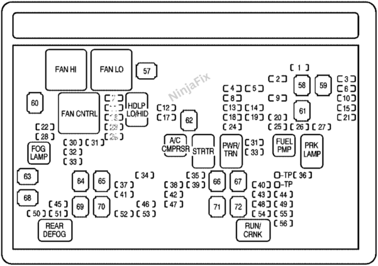
Under Hood 2011 Chevy Silverado Fuse Box Diagram
Alright folks, let's dive under the hood of your 2011 Chevy Silverado and dissect the ever-important fuse box diagram. Whether you're chasing down a pesky electrical gremlin, planning an aftermarket upgrade, or just expanding your automotive knowledge, understanding this diagram is crucial. Think of it as the roadmap to your truck's electrical nervous system. This isn't just about replacing a blown fuse; it's about understanding the why and how of your Silverado's electrical functions.
Why the Diagram Matters
The fuse box diagram is your go-to resource for several key scenarios:
- Troubleshooting Electrical Issues: A malfunctioning component? The diagram helps you pinpoint the circuit, identify the relevant fuse or relay, and start your diagnostic process.
- Adding Aftermarket Accessories: Planning to install new lights, a sound system, or a trailer brake controller? The diagram shows you where to safely tap into existing circuits or add dedicated fuses.
- Preventing Electrical Overloads: Understanding the amperage ratings of different circuits helps you avoid overloading them, which can lead to blown fuses, damaged components, or even electrical fires.
- General Vehicle Maintenance: Familiarizing yourself with the fuse box layout and functions empowers you to perform basic electrical maintenance, saving time and money.
Key Specs and Main Parts
Your 2011 Silverado typically has two main fuse box locations: one under the hood and one inside the cab. We're focusing on the under-hood box in this article because it deals with higher-current circuits and is often the source of many common electrical issues. Here's a breakdown of the key specs and components you'll encounter:
- Fuse Box Location: Typically located on the driver's side of the engine compartment, near the battery. Look for a black plastic box with a removable cover.
- Fuses: These are the sacrificial lambs of your electrical system. They're designed to blow and break the circuit when the current exceeds a safe level, protecting more expensive components. Common types include blade fuses (ATO, mini-ATO, and maxi-fuses).
- Relays: These are electrically operated switches. They use a small control current to switch a larger current on or off. Relays are used to control high-power devices like headlights, starter motors, and fuel pumps.
- Circuit Breakers: These are resettable fuses. Instead of blowing and needing replacement, they trip open when overloaded and can be reset once the overload is removed.
- Bus Bars: These are metal strips that distribute power from the battery to the various fuses and relays.
- Connectors: These connect the fuse box to the vehicle's wiring harness. They can be a source of problems if they become corroded or loose.
Decoding the Symbols: Lines, Colors, and Icons
The fuse box diagram uses a standardized set of symbols and conventions to represent different electrical components and their connections. Here's a rundown of the most common ones:
- Lines: Solid lines represent wires connecting different components. Dashed lines may represent ground connections or internal connections within a component.
- Colors: Wire colors are often indicated on the diagram, which is *extremely* helpful for tracing circuits. Common colors include red (power), black (ground), and various other colors for specific functions (e.g., blue for headlights, yellow for turn signals).
- Icons:
- Fuse Icon: A zig-zag line enclosed in a rectangular shape. The amperage rating is usually indicated next to the icon.
- Relay Icon: A square or rectangle with a coil symbol inside, representing the relay's electromagnet. Terminals are marked with numbers or letters.
- Circuit Breaker Icon: Similar to a fuse icon but with a small switch symbol next to it.
- Ground Symbol: A series of horizontal lines, indicating a connection to the vehicle's chassis for grounding.
Understanding these symbols is crucial for correctly interpreting the diagram and tracing electrical circuits.
How It Works: The Electrical Flow
Let's trace a simple circuit to illustrate how the system works. Imagine your headlights. The process typically goes something like this:
- The battery provides the initial power source.
- The power flows through a main fuse (often a maxi-fuse) to protect the entire system.
- From there, it goes to the headlight switch.
- When you turn on the headlights, the switch activates a relay.
- The relay then closes, allowing power to flow from the battery, through a dedicated headlight fuse, and finally to the headlights themselves.
- The circuit is completed through a ground connection back to the battery.
This illustrates the basic principle of electrical flow. The fuse protects the headlights and wiring from overcurrent. The relay allows a small switch to control a high-power circuit. And the ground connection provides a return path for the current.
Real-World Use: Basic Troubleshooting Tips
Here are some common scenarios and how the fuse box diagram can help:
- Headlights Not Working: Check the headlight fuse first. If it's blown, replace it with a fuse of the *same amperage rating*. If it blows again immediately, there's likely a short circuit in the headlight wiring or the headlights themselves. Use the diagram to trace the wiring and look for damage. Also check the headlight relay.
- Power Windows Not Working: Consult the diagram to locate the power window fuse. If it's good, check the power window relay and the window motor itself. A faulty window motor is a common culprit.
- Radio Not Working: Same process as above. Check the radio fuse, the radio relay (if applicable), and the wiring connections to the radio.
Remember: Always disconnect the battery's negative terminal before working on any electrical components.
Safety First: Identifying Risky Components
Working with electrical systems can be dangerous. Here are some components to be particularly cautious around:
- Battery: Contains corrosive acid and can produce explosive gases. Always wear safety glasses and gloves when working with the battery.
- High-Current Fuses and Relays: These handle large amounts of current and can generate heat. Avoid touching them while the engine is running or the ignition is on.
- Wiring Harness: Damaged or exposed wiring can create short circuits and electrical shocks. Inspect wiring carefully for damage and repair any issues before working on the system.
- Airbag System: The airbag system is electrically triggered and can deploy unexpectedly if handled improperly. Never tamper with airbag wiring or components. If you suspect a problem with the airbag system, consult a qualified technician.
Always prioritize safety when working on your vehicle's electrical system.
By understanding the fuse box diagram, you’ll be well-equipped to troubleshoot electrical issues, add aftermarket accessories, and maintain your 2011 Chevy Silverado’s electrical system safely and effectively. The knowledge gained will save you time and money, and give you a deeper understanding of your truck.
To further assist you, we have a detailed and printable version of the 2011 Chevy Silverado Under-Hood Fuse Box Diagram available for download. Use it as a reference guide in your garage for all your electrical projects. Happy wrenching!