
Understanding Electrical Wiring Diagrams
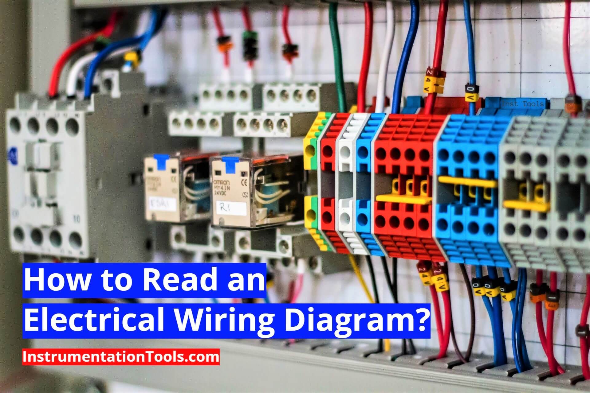
Electrical wiring diagrams are the roadmaps of your vehicle's electrical system. They might seem intimidating at first glance, but understanding them is crucial for effective diagnostics, repairs, and even modifications. Think of them as a detailed recipe book for tracing circuits, identifying components, and ultimately, solving electrical problems without resorting to guesswork. Whether you're diagnosing a faulty sensor, installing aftermarket lights, or even just trying to understand how your car's system works, the ability to read and interpret these diagrams is an invaluable skill.
Purpose of Electrical Wiring Diagrams
Why bother learning to read these diagrams? The answer lies in their utility. They offer several key advantages:
- Troubleshooting: When something goes wrong, a wiring diagram helps you trace the circuit from the power source to the faulty component, pinpointing the location of breaks, shorts, or other issues.
- Repairs: Once you've identified the problem, the diagram guides you in replacing or repairing the damaged wiring or components accurately.
- Modifications: Planning to install that new sound system, custom lighting, or performance upgrades? A wiring diagram ensures you integrate them correctly into the existing electrical system, preventing overloads or damage.
- Understanding Vehicle Systems: Even if you're not actively working on your car, studying the wiring diagrams provides a deeper understanding of how different systems interact and function within your vehicle.
- Preventative Maintenance: Examining the diagram can sometimes reveal potential weak points in the electrical system, allowing you to proactively address them before they cause problems.
Key Specifications and Main Parts
Before diving into the symbology, let's understand the major elements you'll find in a typical wiring diagram. These diagrams aren't meant to be geographically accurate representations of your car, but rather logical maps showing electrical connections and component relationships. Consider this the 'parts list' of our recipe.
- Power Source: Usually the battery, sometimes the alternator, is represented as a symbol connected to the rest of the circuit.
- Ground: The return path for the electricity. Usually represented as a series of horizontal lines diminishing in size.
- Fuses and Circuit Breakers: Protective devices that interrupt the circuit when an overload occurs. Fuses are often shown as rectangles with a line through them, while circuit breakers have more complex symbols.
- Relays: Electrically operated switches that control higher-current circuits. Important for controlling things like headlights and fuel pumps without overloading the main switches.
- Switches: Manual or automatic devices that open or close circuits. Symbols vary depending on the type of switch (toggle, push-button, etc.).
- Sensors: Devices that measure physical parameters (temperature, pressure, speed, etc.) and convert them into electrical signals.
- Actuators: Components that perform actions based on electrical signals (motors, solenoids, injectors, etc.).
- Wiring Harnesses and Connectors: Wires bundled together for protection and organization. Connectors are used to join different wiring harnesses or connect components. Each wire in the harness is usually labeled with a unique identifier.
- Control Modules (ECUs): The "brains" of the operation. They receive signals from sensors, process the data, and send commands to actuators.
Understanding Symbols: The Visual Language
Decoding the symbols is crucial to reading a wiring diagram. Think of these as the individual ingredients and techniques described in our recipe.
Lines: The Pathways
- Solid Lines: Represent wires carrying electrical current. The thicker the line, the higher the current carrying capacity.
- Dashed Lines: Often indicate shielded wires or communication links, such as those used in a Controller Area Network (CAN) bus.
- Arrows: Indicate the direction of current flow.
- Numbering: Wires are often labeled with numbers or alphanumeric codes to identify their function and destination.
Colors: The Identifiers
Wire colors are typically abbreviated (e.g., "BLU" for blue, "RED" for red, "GRN" for green, "BLK" for black, "WHT" for white, "YEL" for yellow). Knowing your color codes is critical when tracing wires in the car itself. Sometimes a wire will be two colors such as 'BLU/RED' which means a blue wire with a red stripe.
Icons: The Components
Each electrical component has a specific icon. Here are a few common examples:
- Resistor: A zig-zag line.
- Capacitor: Two parallel lines.
- Inductor: A coil symbol.
- Diode: A triangle pointing to a line.
- Transistor: A more complex symbol, varying depending on the type (NPN or PNP).
- Ground: Usually three horizontal lines, decreasing in length.
- Battery: A series of alternating long and short parallel lines.
How It Works: Tracing the Circuit
Now, let's see how these elements come together. Here's the basic process of reading a wiring diagram:
- Identify the Component: Locate the component you're interested in (e.g., a fuel pump, headlight, or sensor).
- Find the Power Source: Trace the wire connected to the component back to its power source (battery, ignition switch, etc.).
- Follow the Circuit: Follow the circuit path, noting any fuses, relays, switches, or other components along the way. Pay attention to wire colors and numbers.
- Identify the Ground: Ensure the component has a proper ground connection. A missing or faulty ground is a common cause of electrical problems.
- Understand the Control Logic: For more complex circuits, understand how the control module (ECU) interacts with the component and other sensors or actuators.
It's important to remember that wiring diagrams don't always represent the physical layout of the wiring. Instead, they illustrate the electrical connections in a logical manner. You'll need to correlate the diagram with the actual wiring in the vehicle, using wire colors, numbers, and component locations.
Real-World Use: Basic Troubleshooting Tips
Let's say your car's headlights aren't working. Here's how a wiring diagram can help:
- Consult the Diagram: Find the headlight circuit in the wiring diagram.
- Check the Fuse: Locate the fuse for the headlights. Use a multimeter or test light to confirm that the fuse is good.
- Test the Relay: If the fuse is good, check the headlight relay. You can test the relay by swapping it with a known good relay or by using a multimeter to check its continuity.
- Trace the Wiring: If the relay is good, trace the wiring from the relay to the headlights, looking for any breaks, shorts, or loose connections. Pay particular attention to connectors.
- Check the Ground: Verify that the headlights have a good ground connection.
By systematically tracing the circuit using the wiring diagram, you can isolate the problem area and perform the necessary repairs.
Safety First: Handle with Care
Working with electrical systems can be dangerous if you don't take precautions. Always disconnect the battery's negative terminal before working on any electrical component. This prevents accidental short circuits and potential electric shock.
Certain components, such as the airbag system and the anti-lock braking system (ABS), require specialized knowledge and handling procedures. If you're not comfortable working with these systems, it's best to consult a qualified mechanic. Always use the correct tools and follow proper safety procedures when working with electrical components.
Additionally, be wary of high-voltage components, particularly in hybrid and electric vehicles. These systems can deliver lethal shocks, even when the vehicle is turned off. Always follow the manufacturer's recommendations for servicing these systems.
Remember that the diagram is only as helpful as your ability to use it safely and effectively.
Ready to put your knowledge to the test? We have a sample wiring diagram file available for download. This will allow you to practice tracing circuits and identifying components in a safe and controlled environment. Download it and start honing your skills!