V6 Engine Diagram 3.8 Mustang Vacuum Diagram
Alright, let's dive into the vacuum system of a 3.8L V6 Mustang. A solid understanding of this system is crucial, whether you're chasing down a pesky check engine light, improving your engine's performance, or just deepening your mechanical knowledge. We’re focusing on the vacuum diagram specifically, as it's the roadmap to understanding how all these components interact. We have the V6 Engine Diagram 3.8 Mustang Vacuum Diagram file available for download, and we'll be referencing it throughout this explanation.
Purpose of the Vacuum Diagram
The vacuum diagram is your bible when it comes to diagnosing and repairing anything related to the vacuum system. Think of it as a plumbing schematic for your engine's air management. Its primary purposes include:
- Troubleshooting Vacuum Leaks: Vacuum leaks can cause a multitude of problems, from rough idling to poor fuel economy and even stalling. The diagram pinpoints the location of each vacuum line and component, allowing you to systematically check for leaks using a vacuum gauge or by visually inspecting for cracks and disconnections.
- Understanding Engine Controls: Many engine control systems, like the EGR (Exhaust Gas Recirculation) and PCV (Positive Crankcase Ventilation) systems, rely on vacuum to function correctly. The diagram shows how these systems are connected and how they operate in relation to engine vacuum.
- Performing Repairs and Replacements: When replacing vacuum lines or components, the diagram ensures you reconnect everything correctly. Incorrect connections can lead to serious engine problems.
- Performing Modifications: If you're planning any modifications that affect the intake or exhaust systems, the vacuum diagram provides valuable information on how these changes might impact the vacuum system.
Key Specs and Main Parts
The 3.8L V6 Mustang's vacuum system comprises several key components, all interconnected by a network of vacuum lines. Here are some of the main players:
- Intake Manifold: This is where the engine vacuum originates. The manifold pressure (the vacuum) is highest at idle and decreases as the throttle opens.
- Vacuum Lines: These hoses carry vacuum to various components. They come in different diameters and materials, depending on their function and location. Over time, these lines can become brittle and crack, leading to vacuum leaks.
- PCV Valve (Positive Crankcase Ventilation): This valve regulates the flow of crankcase gases back into the intake manifold. It's crucial for reducing emissions and preventing pressure buildup in the crankcase. A faulty PCV valve can cause excessive oil consumption or rough idling.
- EGR Valve (Exhaust Gas Recirculation): The EGR valve reduces NOx (oxides of nitrogen) emissions by recirculating a portion of the exhaust gas back into the intake manifold. The vacuum diaphragm controls the EGR valve, opening and closing it based on engine load and speed.
- Vacuum Reservoir: This canister stores vacuum to provide a consistent source of vacuum for certain components, such as the climate control system and cruise control.
- Vacuum Check Valves: These one-way valves prevent vacuum from bleeding off when the engine is under load.
- Fuel Pressure Regulator: Regulates the pressure of the fuel supplied to the injectors. Engine vacuum is used as a reference point to adjust fuel pressure.
- MAP Sensor (Manifold Absolute Pressure): While technically an electronic sensor, it measures the pressure in the intake manifold. It's not strictly part of the vacuum system itself, but its readings are directly related to the engine vacuum. The PCM (Powertrain Control Module) uses this data to calculate the engine's air-fuel ratio.
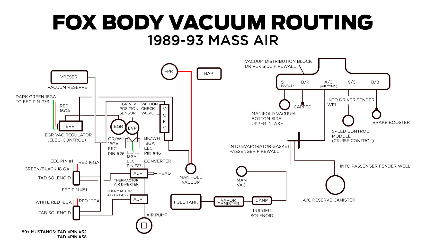
Understanding Symbols in the Vacuum Diagram
The vacuum diagram uses a standardized set of symbols to represent different components and connections. Here’s a breakdown:
- Solid Lines: These represent vacuum lines. The thickness of the line doesn't usually indicate the diameter of the hose, but rather highlights important connections.
- Dotted Lines: These often indicate vacuum lines that are part of a sub-system, or lines that are less critical to the engine's operation. In some cases, they might represent lines that are only present on certain model years or with specific options.
- Circles/Ovals: These typically represent vacuum reservoirs or other holding tanks.
- Squares/Rectangles: These usually represent switches, solenoids, or valves.
- Arrows: Indicate the direction of vacuum flow.
- Color Coding: While not always present on all diagrams, color coding can be helpful. For example, blue might indicate lines related to the EGR system, while green might indicate lines related to the PCV system. Refer to the specific diagram's legend for color code interpretations.
How the Vacuum System Works
The engine's vacuum system operates based on the principle of pressure differential. The intake manifold, when the engine is running, creates a vacuum (a lower pressure than atmospheric pressure). This vacuum is then used to control various components, as detailed below:
When the engine is running, the movement of the pistons creates a vacuum inside the intake manifold. The higher the engine speed and the more closed the throttle plate, the higher the vacuum. This vacuum is then distributed through vacuum lines to various components:
- PCV System: The vacuum draws crankcase gases, which contain combustion byproducts and unburnt fuel, through the PCV valve and into the intake manifold, where they are burned. This prevents pressure buildup in the crankcase and reduces emissions.
- EGR System: When the engine is warm and under certain driving conditions, the vacuum signal to the EGR valve allows exhaust gas to flow into the intake manifold. This lowers combustion temperatures, reducing NOx emissions.
- Fuel Pressure Regulator: The vacuum signal to the fuel pressure regulator adjusts the fuel pressure based on engine load. As the vacuum decreases (under acceleration), the fuel pressure increases to provide more fuel.
- Vacuum Accessories: Vacuum can operate the climate control blend doors or power brake boosters.
Real-World Use: Basic Troubleshooting Tips
Here are some common troubleshooting scenarios and how the vacuum diagram can help:
- Rough Idle: A common cause of a rough idle is a vacuum leak. Use the diagram to systematically check each vacuum line and connection. A vacuum gauge can be used to measure the vacuum in the intake manifold. A low reading indicates a leak. You can also use a can of carburetor cleaner and spray small amounts of it onto vacuum lines and connections. If the idle smooths out, you've found the leak.
- High Fuel Consumption: A vacuum leak can also lead to increased fuel consumption. The engine control unit (ECU) compensates for the extra air entering the engine by injecting more fuel. Again, use the diagram to locate and repair any leaks.
- Check Engine Light (CEL): Certain diagnostic trouble codes (DTCs) are related to vacuum system problems. For example, codes related to the EGR system or MAP sensor could indicate vacuum leaks or malfunctioning components. The diagram helps you pinpoint the specific components involved in the error code.
- EGR Valve Problems: If you suspect a faulty EGR valve, check the vacuum line connected to it. Ensure it's properly connected and that there's vacuum present when the engine is warm and under load.
Safety Precautions
While working on the vacuum system, keep these safety precautions in mind:
- Hot Engine Components: Be careful when working around hot engine components, such as the exhaust manifold. Let the engine cool down before starting any repairs.
- Fuel Lines: Be cautious when working near fuel lines. Fuel is flammable, so avoid any sources of ignition.
- Sharp Edges: Many engine components have sharp edges. Wear gloves to protect your hands.
- Proper Ventilation: Work in a well-ventilated area to avoid inhaling harmful fumes.
- High Vacuum Areas: Be careful disconnecting vacuum lines while the engine is running. The sudden suction can be surprising.
- EGR Valve: Exhaust is hot and can cause burns.
Understanding the vacuum system is a critical aspect of maintaining and repairing your 3.8L V6 Mustang. By utilizing the vacuum diagram and following proper safety precautions, you can confidently diagnose and address vacuum-related issues, keeping your engine running smoothly. Remember, you can download the V6 Engine Diagram 3.8 Mustang Vacuum Diagram to help you on your way!