
V6 Engine Ford 4.0 Sohc Engine Diagram
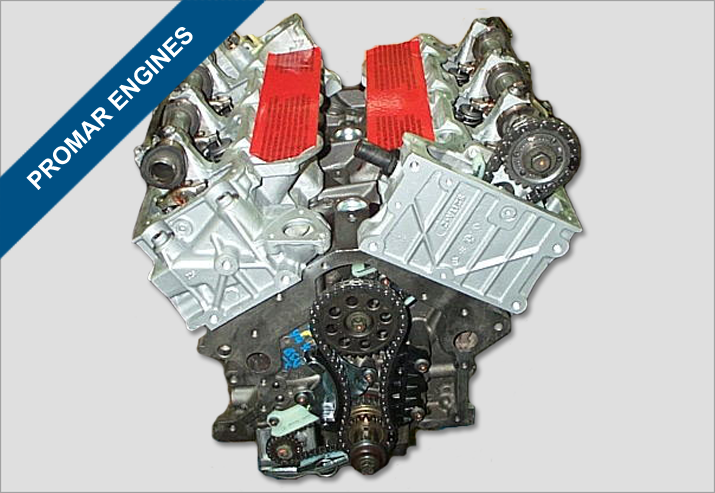
If you're tackling a repair, modification, or just trying to understand the inner workings of your Ford equipped with the 4.0L SOHC V6, a comprehensive engine diagram is absolutely essential. This article serves as your guide to interpreting these diagrams, focusing specifically on the Ford 4.0L Single Overhead Cam (SOHC) engine. We'll break down the key components, symbols, and how the engine functions. Understanding this information empowers you to perform maintenance with confidence, diagnose issues accurately, and potentially save a significant amount of money on repair costs.
Purpose of the 4.0L SOHC Engine Diagram
Engine diagrams aren't just pretty pictures; they're roadmaps to understanding a complex machine. For the 4.0L SOHC, the diagram helps with several key tasks:
- Troubleshooting: Identifying the location of specific components, like sensors or vacuum lines, becomes much easier when you have a visual reference. Want to check the crankshaft position sensor? The diagram shows you where it lives relative to other parts.
- Repair Procedures: Diagrams often illustrate the correct order of disassembly and reassembly. Torque specifications and the orientation of parts are usually included in manuals that reference these diagrams.
- Modifications: If you're considering modifications, the diagram helps you understand the relationships between different systems. For example, if you're planning to install headers, you need to understand the exhaust manifold's relationship to the catalytic converters and O2 sensors.
- Learning: Even if you don't plan on wrenching, a diagram helps you appreciate the engineering behind your engine. It's a valuable tool for anyone who wants to understand how their vehicle works.
Key Specs and Main Parts of the 4.0L SOHC V6
Before diving into the diagram itself, let's review some key specs and identify the major components. The 4.0L SOHC V6 was used in various Ford models, including the Explorer, Ranger, Mustang, and others. Here's a brief overview:
- Displacement: 4.0 Liters (3996 cc)
- Configuration: V6 (6 cylinders arranged in a 'V' shape)
- Valve Train: Single Overhead Cam (SOHC) – One camshaft per cylinder bank actuating the valves. This is in contrast to DOHC (Dual Overhead Cam), which has two camshafts per bank.
- Firing Order: Typically 1-4-2-5-3-6 (Consult your specific vehicle manual for confirmation).
- Fuel System: Sequential Fuel Injection (SFI). Each injector fires individually in the correct sequence.
Main Components (often shown in detail on the diagram):
- Cylinder Block: The engine's main structure, housing the cylinders.
- Cylinder Heads: Contain the combustion chambers, valves, and spark plugs.
- Camshaft(s): Controls the opening and closing of the valves. In the SOHC configuration, there's one camshaft per cylinder bank.
- Valves (Intake and Exhaust): Control the flow of air/fuel mixture into and exhaust gases out of the cylinders.
- Pistons: Move up and down inside the cylinders, driven by the combustion process.
- Connecting Rods: Connect the pistons to the crankshaft.
- Crankshaft: Converts the reciprocating motion of the pistons into rotational motion.
- Intake Manifold: Distributes the air/fuel mixture to the cylinders.
- Exhaust Manifolds: Collect exhaust gases from the cylinders.
- Fuel Injectors: Spray fuel into the intake ports.
- Throttle Body: Controls the amount of air entering the engine.
- Sensors: MAP sensor (Manifold Absolute Pressure), MAF sensor (Mass Air Flow), Crankshaft Position Sensor (CKP), Camshaft Position Sensor (CMP), Oxygen Sensors (O2), Coolant Temperature Sensor (CTS), etc. These are crucial for the engine control unit (ECU) to function correctly.
- Engine Control Unit (ECU): The engine's computer, which controls various engine functions based on sensor inputs.
- Ignition System: Includes the ignition coils, spark plugs, and wiring, responsible for igniting the air/fuel mixture.
- Water Pump: Circulates coolant to regulate engine temperature.
- Oil Pump: Circulates oil to lubricate engine components.
Understanding the Diagram: Symbols, Lines, and Colors
Engine diagrams use standardized symbols and conventions. Here's a breakdown of what you might encounter:
- Lines: Different types of lines represent different systems:
- Solid Lines: Typically represent fluid lines (fuel, coolant, oil). The thickness of the line can indicate the size of the pipe/hose.
- Dashed Lines: Often represent vacuum lines or control signals.
- Dotted Lines: Might indicate internal passages within the engine block or head.
- Thick Lines: Can signify power or signal wires within the electrical system.
- Colors: Colors can be used to differentiate between systems. For example:
- Red: Often used for fuel lines.
- Blue: Typically used for coolant lines.
- Black: Can represent vacuum lines or ground connections.
- Yellow/Green: Often used for electrical wiring.
- Symbols: Specific symbols represent components:
- Resistors: A jagged line.
- Capacitors: Two parallel lines.
- Inductors: A coiled wire.
- Sensors: Represented by unique symbols depending on the type of sensor (e.g., a square with an arrow pointing in for a flow sensor).
- Valves: Can be represented by various symbols depending on the type (e.g., check valve, solenoid valve).
Always refer to the diagram's legend or key to understand the specific meaning of each line, color, and symbol used in that particular diagram. There can be slight variations between diagrams from different sources.
How the 4.0L SOHC V6 Works: A Brief Overview
The 4.0L SOHC V6 operates on the four-stroke combustion cycle:
- Intake: The intake valve opens, and the piston moves down, drawing air/fuel mixture into the cylinder.
- Compression: The intake valve closes, and the piston moves up, compressing the air/fuel mixture.
- Combustion: The spark plug ignites the compressed mixture, creating an explosion that forces the piston down.
- Exhaust: The exhaust valve opens, and the piston moves up, pushing the exhaust gases out of the cylinder.
The SOHC (Single Overhead Cam) design means that each bank of cylinders has a single camshaft located above the cylinder head. This camshaft actuates the valves directly or via rocker arms. The camshaft is driven by the crankshaft via a timing chain or belt. The ECU controls the fuel injection and ignition timing to optimize performance and efficiency.
Real-World Use: Basic Troubleshooting Tips
Using the engine diagram, you can perform basic troubleshooting. Here are a few examples:
- Vacuum Leaks: Use the vacuum line diagram to trace the lines and check for cracks or disconnections. Vacuum leaks can cause poor idle, reduced fuel economy, and engine misfires.
- Sensor Issues: If you get a check engine light related to a specific sensor (e.g., MAP sensor), use the diagram to locate the sensor and check its wiring and connections. You can also use a multimeter to test the sensor's voltage or resistance.
- Coolant Leaks: Follow the coolant lines in the diagram to identify potential leak points, such as hoses, the water pump, or the radiator.
- Fuel Delivery Problems: The fuel system diagram can help you trace the fuel lines from the fuel tank to the fuel injectors. This can help you identify potential issues, such as clogged fuel filters or faulty fuel pumps.
Always consult your vehicle's service manual for specific troubleshooting procedures and diagnostic codes.
Safety Considerations
Working on an engine involves inherent risks. Here are some important safety precautions:
- Disconnect the Battery: Before working on any electrical components, disconnect the negative battery cable to prevent electrical shocks or short circuits.
- Fuel System: Fuel is highly flammable. Never smoke or work near open flames when working on the fuel system. Relieve fuel pressure before disconnecting fuel lines.
- Cooling System: The cooling system is pressurized and can be extremely hot. Allow the engine to cool completely before opening the radiator cap or working on coolant lines.
- Moving Parts: Be aware of moving parts, such as the serpentine belt, pulleys, and fans. Keep your hands and clothing clear of these parts when the engine is running.
- Exhaust System: The exhaust system gets extremely hot. Allow it to cool completely before working on it.
- Always wear safety glasses and gloves when working on your engine.
Specifically, be cautious around the ignition system. High voltage is present at the ignition coils and spark plugs, even with the key off. Use insulated tools and follow proper procedures to avoid electric shock.
With a clear understanding of the 4.0L SOHC V6 engine diagram, you're well-equipped to tackle various maintenance and repair tasks. Remember to always prioritize safety and consult your vehicle's service manual for specific procedures and specifications.
To further aid you in your endeavors, we have a detailed, printable 4.0L SOHC Engine Diagram file available for download. This diagram offers high-resolution details that can be invaluable when working on your engine. Please contact us to get the file.