Vacuum Hose 2002 Dodge Ram 1500 4.7 Vacuum Diagram
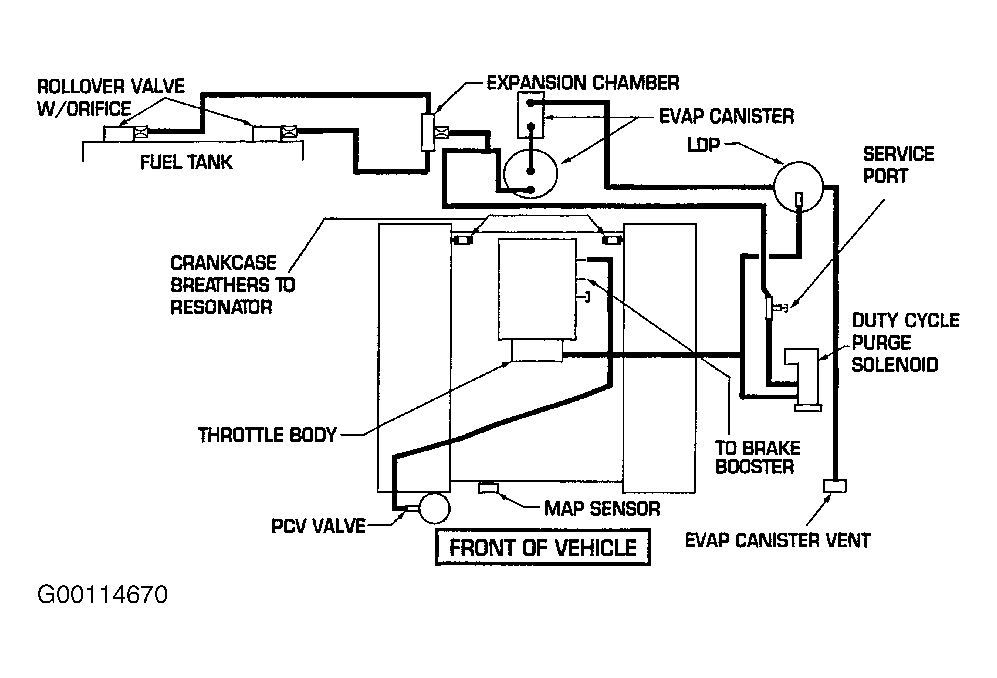
Alright, let's dive into the vacuum hose system of your 2002 Dodge Ram 1500 with the 4.7L engine. Understanding this system is crucial for diagnosing and resolving a surprising number of performance issues. We're talking everything from rough idling and poor fuel economy to malfunctioning HVAC controls and even transmission problems. This article will give you the knowledge to confidently tackle vacuum hose-related issues on your own. And to make it even easier, we have the actual vacuum diagram you can download, allowing you to see the exact layout for your specific model year.
Purpose of the Vacuum Diagram
Why bother understanding your vacuum system? The vacuum diagram is your roadmap to a properly functioning engine. It's not just a pretty picture; it's the key to:
- Troubleshooting Performance Issues: Vacuum leaks are notorious for mimicking other engine problems. The diagram helps you pinpoint the source.
- Performing Repairs: Replacing hoses correctly after maintenance is essential to avoid creating new problems.
- Understanding Engine Operation: Getting familiar with the vacuum system improves your overall understanding of how your engine and its auxiliary systems work.
- Modifying or Restoring Your Vehicle: When making modifications or restoring a vehicle, a clear understanding of the original vacuum routing is essential for maintaining proper function.
Key Specs and Main Parts
Before we jump into the diagram itself, let's familiarize ourselves with the key components and specifications. The vacuum system on the 2002 Dodge Ram 1500 4.7L relies on the manifold vacuum, which is the negative pressure created within the intake manifold as the pistons move down and draw air into the cylinders. This vacuum is then harnessed to operate various components. Here's a rundown:
Main Components:
- Intake Manifold: The heart of the vacuum system. This is where the vacuum is generated.
- Vacuum Hoses: These rubber or plastic hoses act as the arteries and veins of the system, carrying vacuum to different components.
- Vacuum Reservoir (Vacuum Canister): A holding tank for vacuum, typically located in the engine bay. It provides a stable vacuum source, especially when engine vacuum fluctuates.
- Check Valves: One-way valves that allow vacuum to flow in only one direction. They prevent vacuum from being lost when engine vacuum drops.
- EGR Valve (Exhaust Gas Recirculation): Reduces NOx emissions by recirculating a portion of the exhaust gas back into the intake manifold. It is controlled by vacuum.
- PCV Valve (Positive Crankcase Ventilation): Vents crankcase fumes back into the intake manifold to be burned, reducing emissions and preventing pressure buildup.
- HVAC Controls: Vacuum actuators control the blend doors and mode doors within the HVAC system, directing airflow.
- Fuel Pressure Regulator: Some fuel pressure regulators are vacuum-operated, adjusting fuel pressure based on engine load.
- Throttle Body: While not a direct vacuum component, the throttle body's position affects manifold vacuum.
Common Hose Sizes:
You'll typically find hoses in sizes ranging from 1/8" to 1/4" inner diameter. Make sure to use hoses specifically designed for vacuum applications; fuel lines are not suitable and will collapse under vacuum.
Understanding the Symbols on the Diagram
The vacuum diagram uses a standard set of symbols to represent different components and connections. Deciphering these symbols is critical to understanding the routing.
- Solid Lines: Represent vacuum hoses. The thickness of the line may indicate the hose diameter.
- Dotted Lines: Often indicate electrical connections or control signals related to the vacuum system (e.g., a vacuum solenoid valve being controlled by the PCM).
- Arrows: Show the direction of vacuum flow.
- Circles/Ovals: Typically represent vacuum actuators or solenoids.
- Rectangles/Squares: May represent electronic control units (ECUs) or other electrical components involved in the vacuum system's operation.
- T-Connectors/Y-Connectors: Show where one vacuum line splits into two or more lines.
- Check Valves: Represented by a symbol resembling a diode, with an arrow indicating the direction of allowed flow.
Color-coding on the diagram, if present, is usually arbitrary and meant for visual clarity, but the legend, which we have available with the file download, will note the hose material if present. Don't rely solely on color to identify hoses, as they may fade or be replaced with different colors over time. Always trace the hose back to its origin and destination using the diagram.
How the Vacuum System Works
The engine creates vacuum in the intake manifold. This vacuum is then distributed through a network of hoses to various components that rely on it to function. Let's consider a few key systems:
- EGR System: The PCM (Powertrain Control Module) controls a vacuum solenoid that regulates the amount of vacuum applied to the EGR valve. When vacuum is applied, the EGR valve opens, allowing exhaust gas to flow into the intake manifold.
- PCV System: A constant vacuum is applied to the PCV valve, drawing crankcase fumes into the intake manifold. The PCV valve regulates the flow of these fumes to prevent excessive vacuum in the crankcase.
- HVAC System: Vacuum actuators control the blend doors and mode doors within the HVAC system. When vacuum is applied to an actuator, it moves a door to direct airflow. A loss of vacuum in this system can cause the HVAC to default to defrost mode.
A vacuum leak anywhere in the system weakens the vacuum available to all components, leading to malfunctions and performance issues. That's why a systematic approach to troubleshooting is vital.
Real-World Use: Basic Troubleshooting Tips
So, how do you use this knowledge to fix your Ram? Here are some practical tips:
- Visual Inspection: The first step is always a thorough visual inspection. Look for cracked, brittle, or disconnected hoses. Pay close attention to the hose ends, where they are most likely to fail.
- Vacuum Gauge: A vacuum gauge is your best friend. Connect it to a manifold vacuum source and check the reading at idle. A low or fluctuating reading indicates a vacuum leak or other engine problem. A healthy engine should typically pull around 17-22 inches of mercury (inHg) at idle at sea level.
- Smoke Test: A smoke test is a highly effective way to find vacuum leaks. Introduce smoke into the vacuum system and look for where it escapes. This is especially useful for finding small leaks that are difficult to detect visually.
- Carburetor Cleaner/Propane Enrichment Test: Carefully spray small amounts of carburetor cleaner or propane around potential leak sources. If the engine RPM increases, you've likely found a leak. Use extreme caution with this method, as carburetor cleaner and propane are flammable.
- Systematic Approach: Use the vacuum diagram to systematically check each hose and component. Don't just randomly poke around; follow the routing to pinpoint the problem.
Safety Considerations
Working on the vacuum system is generally safe, but there are a few potential hazards to be aware of:
- Hot Engine Components: Be careful not to touch hot engine components, such as the exhaust manifold or catalytic converter.
- Flammable Liquids: As mentioned earlier, use extreme caution when using carburetor cleaner or propane to find vacuum leaks. Keep a fire extinguisher nearby and avoid spraying near open flames or sparks.
- Sharp Edges: Be aware of sharp edges on engine components and use gloves to protect your hands.
- Battery Disconnect: While not always necessary, disconnecting the battery before working on any electrical components related to the vacuum system is a good safety precaution.
By understanding the vacuum system and using the diagram, you can diagnose and repair a wide range of issues on your 2002 Dodge Ram 1500 4.7L. Remember to take your time, be thorough, and always prioritize safety.
We have the complete vacuum diagram file ready for you to download. This will give you a detailed visual guide to help you with your troubleshooting and repairs.