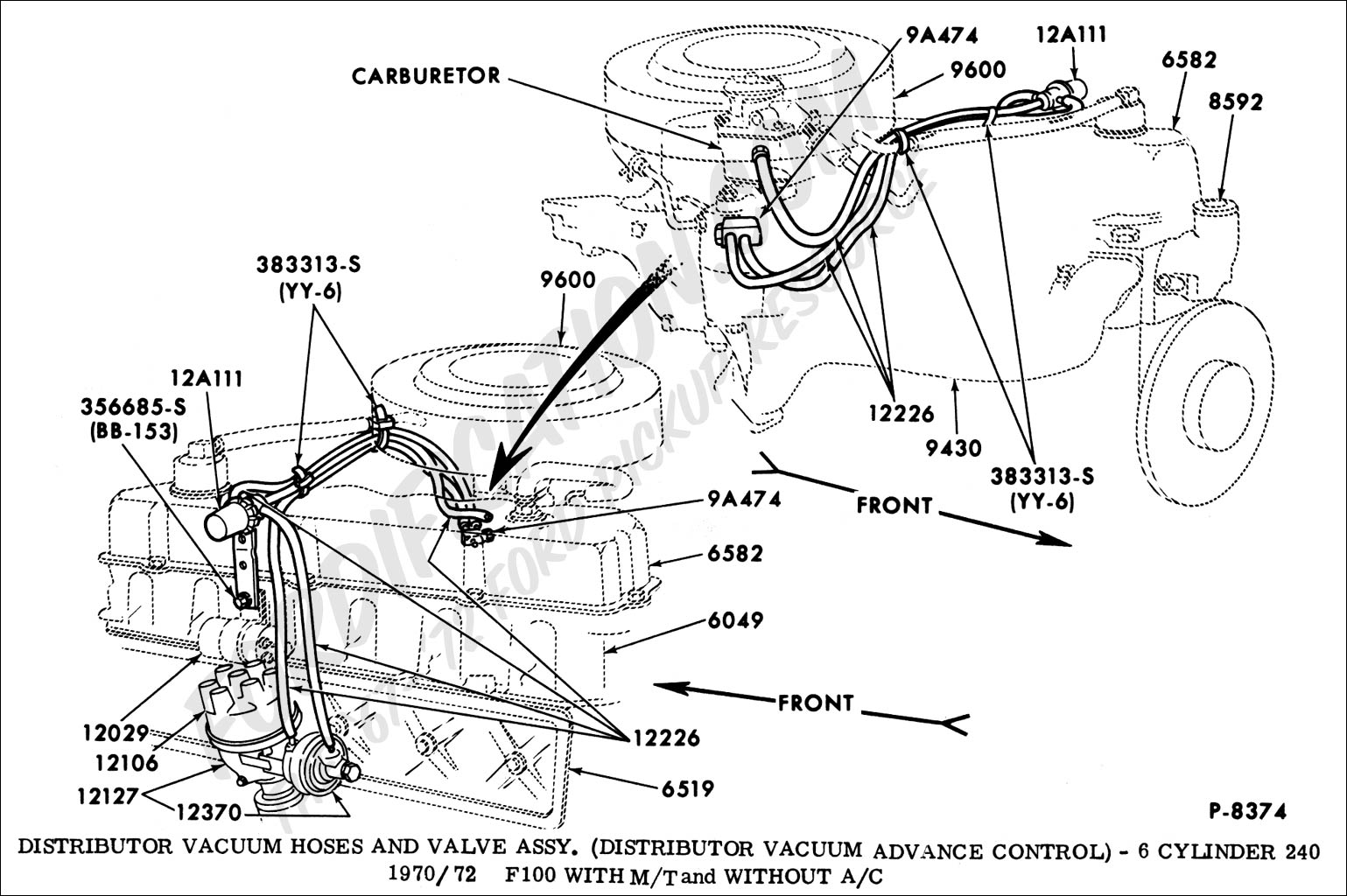
Vacuum Hose Ford 300 Inline 6 Vacuum Diagram
Navigating the vacuum lines on a Ford 300 inline-six engine can seem like deciphering an ancient scroll. But understanding this system is crucial for maintaining optimal engine performance, troubleshooting issues, and even performing certain modifications. This article will break down the vacuum hose diagram for the Ford 300, equipping you with the knowledge to confidently diagnose and repair your engine.
Purpose of the Vacuum Hose Diagram
The vacuum system in your Ford 300 engine isn't just a collection of hoses; it's a carefully orchestrated network that controls various engine and accessory functions. A vacuum diagram is essential for several reasons:
- Repairs: Identifying the correct hose routing is paramount when replacing cracked, brittle, or disconnected vacuum lines. Incorrect connections can lead to poor engine performance, emissions failures, and even component damage.
- Troubleshooting: Vacuum leaks are a common cause of engine problems. A diagram allows you to systematically trace hoses and identify potential leak sources.
- Learning: Understanding the vacuum system helps you grasp the overall operation of the engine and its various subsystems.
- Modifications: If you're planning any performance upgrades or modifications, a thorough understanding of the vacuum system is essential to ensure proper function and avoid unintended consequences.
Key Specs and Main Parts
The Ford 300 inline-six engine, produced from the mid-1960s through the late 1990s, underwent various revisions throughout its lifespan. Consequently, vacuum diagrams can differ slightly depending on the year and specific model. However, the core components and their functions remain largely consistent. Some of the key parts of the vacuum system include:
- Vacuum Source: Usually tapped from the intake manifold, providing the negative pressure that drives the entire system.
- Carburetor: The carburetor utilizes vacuum signals for various functions, including choke operation, idle speed adjustment, and fuel enrichment.
- Distributor: Vacuum advance and retard mechanisms in the distributor rely on vacuum to optimize ignition timing based on engine load and speed.
- EGR Valve (Exhaust Gas Recirculation): Controlled by vacuum, the EGR valve recirculates a portion of the exhaust gases back into the intake manifold to reduce NOx emissions.
- PCV Valve (Positive Crankcase Ventilation): This valve regulates the flow of crankcase vapors back into the intake manifold for combustion.
- Charcoal Canister: Part of the evaporative emissions (EVAP) system, the charcoal canister stores fuel vapors from the fuel tank and carburetor, which are then purged back into the engine via vacuum.
- Vacuum Reservoir (or Canister): Some models use a vacuum reservoir to maintain a consistent vacuum supply for certain accessories, such as the heater and air conditioning controls.
- Vacuum Check Valves: These one-way valves prevent vacuum loss in certain circuits, ensuring proper operation of specific components.
- Vacuum Modulators (Transmission): Some automatic transmissions use vacuum to control shift timing and firmness.
Symbols and Lines in a Vacuum Diagram
Vacuum diagrams use standardized symbols and line types to represent different components and connections. Understanding these conventions is crucial for accurate interpretation:
- Solid Lines: Represent direct vacuum lines.
- Dotted Lines: Indicate ported vacuum lines. Ported vacuum is only present when the throttle plate is opened, whereas manifold vacuum is always present.
- Colored Lines: Some diagrams use color-coded lines to differentiate between different vacuum circuits (e.g., red for distributor advance, blue for EGR). The color coding varies, so always refer to the legend on the specific diagram.
- Circles: Represent vacuum actuators or control valves.
- Squares/Rectangles: Often symbolize electrical components or switches related to the vacuum system.
- "T" Connectors: Indicate a point where a vacuum line splits into multiple branches.
- Arrows: Show the direction of airflow or vacuum within the lines.
Always cross-reference the diagram with the physical components on your engine. Labeling hoses with masking tape and a marker before disconnecting them can prevent errors during reassembly.
How It Works: The Vacuum Symphony
The vacuum system operates on the principle of negative pressure. The engine's intake stroke creates a vacuum in the intake manifold. This vacuum is then harnessed through a network of hoses and control devices to operate various engine and accessory functions.
For instance, the vacuum advance on the distributor uses manifold vacuum to advance the ignition timing as engine load decreases. This improves fuel economy and performance during light-load conditions. The EGR valve uses vacuum to open and recirculate exhaust gases, reducing NOx emissions. The PCV valve regulates crankcase ventilation by drawing harmful vapors from the crankcase and burning them in the engine. The charcoal canister captures fuel vapors from the fuel tank, preventing them from escaping into the atmosphere. The vacuum system provides the negative pressure needed to draw these fumes into the engine to be burned.
The specific operation of each component within the vacuum system is dependent on the engine's operating conditions, which is why a correctly routed system is so critical.
Real-World Use: Basic Troubleshooting
Vacuum leaks are a common problem with older vehicles. Here are some basic troubleshooting tips:
- Visual Inspection: Carefully inspect all vacuum hoses for cracks, brittleness, or disconnections. Pay close attention to areas near heat sources.
- Audible Check: Listen for hissing sounds, which can indicate a vacuum leak.
- Vacuum Gauge: A vacuum gauge can be used to diagnose engine problems related to vacuum leaks or restrictions. Connect the gauge to a manifold vacuum source and observe the readings. A low or erratic reading can indicate a problem.
- Carburetor Cleaner Test: With the engine running, carefully spray small amounts of carburetor cleaner around vacuum hose connections and intake manifold gaskets. If the engine speed changes, it indicates a vacuum leak in that area. Use caution when spraying flammable liquids around a hot engine.
When replacing vacuum hoses, use hoses of the correct size and material. Generic rubber hoses may not be suitable for all applications. Silicone hoses are often a good upgrade for their durability and resistance to heat and chemicals.
Safety Considerations
While working on the vacuum system is generally safe, there are a few safety considerations:
- Hot Engine: Avoid working on the vacuum system when the engine is hot. Exhaust manifolds and other components can cause burns.
- Flammable Liquids: Use caution when using carburetor cleaner or other flammable liquids to locate vacuum leaks. Keep a fire extinguisher nearby.
- Sharp Objects: Be careful when handling tools and hoses to avoid cuts and punctures.
- Battery Disconnect: Although not strictly necessary for most vacuum system repairs, disconnecting the battery can provide an extra margin of safety.
The EGR valve can be extremely hot after the engine has been running. Allow the engine to cool before attempting to remove or inspect it.
Accessing the Vacuum Diagram
Having a proper vacuum diagram specific to your Ford 300's year and model is crucial. We have a digital copy of a common Ford 300 inline 6 vacuum diagram available for download. This file provides a detailed visual guide to help you understand and troubleshoot your engine's vacuum system. Contact us for download information.
By understanding the purpose, components, and operation of the vacuum system, you can confidently maintain and repair your Ford 300 inline-six engine and ensure it runs smoothly for years to come.